Summary of Adventures in Moteino: Remote temperature monitor
Summary: The article describes building a wireless remote sensor system using Moteino Arduino-compatible RF nodes that broadcast sensor data to a central controller/aggregator. It outlines the hardware choice (Moteino with ATMega328P and SPI RF module), deployment goals, power/range tradeoffs, and notes follow-up work including a modular Mote sketch and backend data processing.
Parts used in the CuPID/Pi Remote Temperature Monitor:
- Moteino (Arduino-compatible) board
- ATMega328P microcontroller (on Moteino)
- RF radio module (Moteino RF board, SPI interfaced)
- Antenna (built into Moteino assembly)
- On-board voltage regulator (on Moteino)
- FTDI cable (for programming and diagnostics)
- Enclosure/box (to house the Moteino)
- Batteries or power source (for remote operation)
Introduction
What every new system design has in common these days is wireless. Like bacon, it just makes everything better. Put a sensor wherever, read it from somewhere else. Put the power and control where you need it. For the CuPID/Pi, it is no different. We want to put our remote sense and control modules out into the wild and read and aggregate them as it makes sense.
Our basic system layout is as below. We’ve got multiple wireless nodes that broadcast data periodically, and a controller/aggregator that will log this data, acknowledge receipt, and do something useful with it. Eventually, we may have intermediate powered nodes that serve to mesh the grid out, but for now, our nodes just send data to the controller.
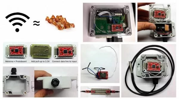
We’re currently using these awesome little RF units, called Moteinos. They are an Arduino clone that can use the standard IDE with their bootloader. They’ve got the ever-so-popular ATMega328P chip that is familiar to anybody working with an Arduino Nano or Uno. The Moteino comes with an RF board using the SPI bus of the microcontroller, available in various frequency flavors, and also in two different power varieties: one for maximum range, and one for maximum battery life. The whole thing comes nicely arranged on a PCB with a built-in voltage regulator, headers to connect our FTDI cable for loading and diagnostics, and an antenna. All for about $20. Really a fantastic deal .. and great customer support. Please patronize them.
Anyhow, so we jammed one of these into a box in another post, and now we’d like to complete the job of creating a general purpose remote wireless node, along with getting it talking and doing something useful.
As a post-note, we took the basics we hashed out here and put them into a modular Mote sketch. This post is still useful for a demonstration of how we put these pieces together.
We also went on to build up the backend data processing, and talk about that elsewhere as well. Check it out.
For more detail: Adventures in Moteino: Remote temperature monitor
- What hardware is used for the wireless nodes?
The nodes use Moteino boards which include an ATMega328P microcontroller and an RF radio module on SPI. - How do nodes communicate with the controller?
The nodes broadcast data periodically via their RF radio modules to a central controller/aggregator. - Can the Moteino be programmed with the Arduino IDE?
Yes, the Moteino is Arduino-compatible and can be used with the standard IDE using its bootloader. - What power and range options are available?
Moteinos are available in two power varieties: one optimized for maximum range and one for maximum battery life. - How is the Moteino programmed or diagnosed?
Programming and diagnostics are done via an FTDI cable connected to the Moteino headers. - Is an enclosure used for the remote node?
Yes, the Moteino is placed in a box or enclosure for deployment. - Does the project include backend data processing?
Yes, the authors mention building backend data processing and a modular Mote sketch in follow-up posts. - Are intermediate mesh nodes part of the initial design?
No, intermediate powered mesh nodes are a possible future enhancement; initial nodes send data directly to the controller.