


Summary of A simple spectrum analyzer using dsPIC30F4011
This project implements a frequency spectrum analyzer using the dsPIC30F4011 microcontroller. The hardware setup conditions input signals through high-impedance resistors and op-amps to protect the microcontroller, utilizing a programmable gain amplifier for signal scaling before ADC conversion. Software components include Microchip's FFT library and a graphic LCD driver to visualize the spectrum of input signals like square waves on an LCD screen.Parts used in the Spectrum Analyzer Project:
- dsPIC30F4011
- Opamp (e.g., LM358 or TL084)
- Power supply
- High impedance resistor (1Mohms)
- Programmable gain amplifier (MCP6S21)
- Graphic LCD
- FFT library code from Microchip
- Graphic LCD driver code
2. Graphic LCD driver code (for line, pixel plot etc).
Graphic LCD showing spectrum of a square wave: -
Description of hardware: -
The dsPIC runs on the internal oscillator of 7.37MHz, which is then raised close to 30MHz using the PLL. This enables the board to run without external oscillators and associated loading capacitors.
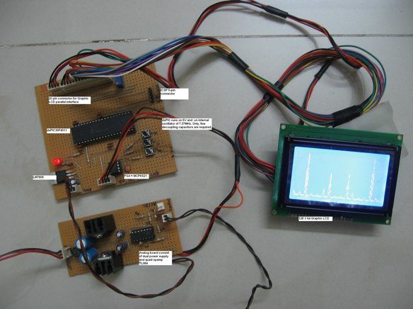
The signal to be analyzed is passed through a high impedance resistor (1Mohms) and then amplified by opamp (TL084). This is done to avoid any high voltage damaging the dsPIC or associated circuit. DC offset is added to the signal to enable it to be measured by ADC (0V to 5V).
A programmable gain amplifier (MCP6S21) is used to scale the signals through software. Otherwise, we had to provide a potentiometer to select different gain. The signal is then fed into analog channel of dsPIC.
For more detail: A simple spectrum analyzer using dsPIC30F4011
Quick Solutions to Questions related to Spectrum Analyzer Project:
-
How does the board run without external oscillators?
The dsPIC runs on an internal oscillator of 7.37MHz raised close to 30MHz using the PLL. -
What is the purpose of the 1Mohm resistor?
It acts as a high impedance resistor to pass the signal while avoiding high voltage damage to the dsPIC. -
Why is DC offset added to the signal?
DC offset enables the signal to be measured by the ADC within the 0V to 5V range. -
Which component scales the signals through software?
A programmable gain amplifier (MCP6S21) is used to scale the signals via software. -
Can different opamps be used in this project?
Yes, any opamp like LM358 or TL084 can be used. -
What software libraries are required for this project?
The project requires the FFT library code from Microchip and Graphic LCD driver code. -
Does the system require a potentiometer for gain selection?
No, a programmable gain amplifier allows scaling through software instead of using a potentiometer. -
What type of signal is shown on the graphic LCD?
The graphic LCD displays the spectrum of a square wave.
Related projects
Audio Spectrum Analyzer
We developed an audio spectrum analyzer as our final project for ECE 4760. This analyzer presented a histogram-style representation of audio signals....
Audio, Sound & Radio · PIC12F675Audio CRO using PIC12F675 Microcontroller
This project is a miniature Audio CRO. For those not familiar with the abbreviation "CRO," it means "Cathode Ray Oscilloscope" and this...
Audio, Sound & RadioBuild a musical EKG with the Freescale FRDM-KL05
Short Introduction: I have been following the Battle of the DreamBoards Championship with interest and I enjoyed the variation of functionality features...
Audio, Sound & RadioPIC MicroController Volume Adjuster Program(Proteus 8 Stimulation)
Hello everyone, The important aspect of every learning is to induce curiosity and doing something meaningful to satisfy that.With the help of...
Audio, Sound & RadioWireless Radio Frequency Module Using PIC Microcontroller
It's a Microcontroller Based DIY Electronics Project. Named Wireless RF Module Using PIC Microcontroller. The RF module is a small electronic circuit...
Audio, Sound & Radio · PIC16F676Shrieker using PIC16F676 Microcontroller
Recently a cell phone ring tone was in the news - it's 17,000 Hertz and meant to be heard by teenagers, but...

Ibrar Ayyub
I am an experienced technical writer holding a Master's degree in computer science from BZU Multan, Pakistan University. With a background spanning various industries, particularly in home automation and engineering, I have honed my skills in crafting clear and concise content. Proficient in leveraging infographics and diagrams, I strive to simplify complex concepts for readers. My strength lies in thorough...