Summary of A PIC16F819 DYMOCLOCK
This project is a simple LED clock and thermometer built around a PIC16F819 (18-pin) using direct LED driving (no decoders/drivers), 27 LEDs arranged in three rows for hours, minutes/seconds/°C, and fine increments, plus a silicon diode as temperature sensor. It runs a 12-hour clock with 2°C thermometer resolution, multiplexed LED tables, and button controls for mode, toggle, and set; compiled with mikroC for a PIC16F819 at 16 MHz.
Parts used in the Simple LED clock with thermometer:
- PIC16F819 microcontroller (18-pin)
- 16 MHz crystal
- 27 LEDs (25 mA each)
- Silicon diode used as temperature sensor
- Push buttons (mode, toggle/advance, set)
- Colored hookup wires for LED wiring
- Power supply (suitable for PIC and LEDs)
- Miscellaneous PCB or protoboard and wiring hardware
I wanted to build a clock as simple as possible :
- built around a little 18 pins PIC
- no 7 segment display, only LEDs
- no decoder, no buffer, no driver for the LED display
- a cheap temperature sensor
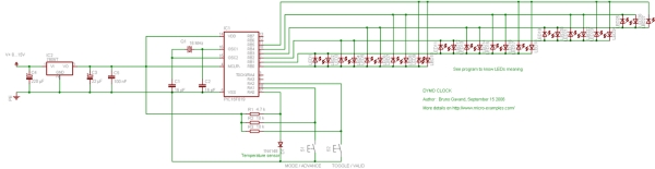
The solution of direct LED driving comes from a Microchip Application Note AN234, and as I’m using 25 mA LEDs, I simply removed all current limiting resistors.
 A silicon diode is used as temperature sensor, and the rest of the circuit is very classic around a PIC16F819 :
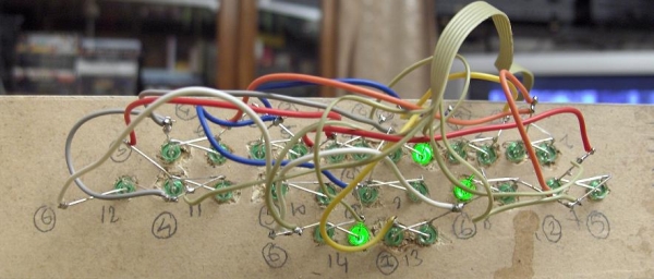
Upper row : hours
Middle row : minutes or seconds or degrees C
Lower row : add it to middle row
The wiring side of the LEDs is a little bit messy,
some colored wires are helpful !
See the source code for LED numbering.
THE SOURCE CODE
*************************************************************************
* file : dymoclock.c
* project : Simple LED clock with thermometer
* author : Bruno Gavand
* compiler : mikroC V6.0.0.0
* date : september 15, 2006
*
* description :
* This is a 12 hours clock with 27 LEDs display, with a 2°C resolution thermometer
*
* target device :
* PIC16F819 with 16 Mhz crystal
*
* configuration bits :
* HS clock
* no watchdog
* no power up timer
* RA5 as MCLR pin
* brown out detect
* LVP disabled
* data EE protect disabled
* ICD disabled
* CCP1 pin on RB2
*
*************************************************************************
*/
/*
* display modes
*/
#define MODE_HOURMN 0 // display hours:minutes
#define MODE_SS 1 // display seconds
#define MODE_TEMP 2 // display temperature
#define MAX_MODE 3 // number off display modes
/*
* buttons
*/
#define BUTTON ((PORTA.F1 == 0) || (PORTA.F2 == 0)) // at least one
#define BUTTON_MODE (PORTA.F1 == 0) // mode / advance
#define BUTTON_TOGGLE (PORTA.F2 == 0) // toggle / valid
#define BUTTON_SET ((PORTA.F1 == 0) && (PORTA.F2 == 0)) // both at the same time
#define TEMP_REF 115 // silicon junction offset : 600 mV
#define MAX_TEMP 20 // number of temperature samples
/*
* LED multiplexing tables
*
* LED index : 1 2 3 4 5 6 7 8 9 10 11 12 13 14 15 16 17 18 19 20 21 22 23 24 25 26 27 28 29 30
* LED number : 1 2 3 4 9 10 5 6 11 12 25 30 7 8 5 10 35 40 45 50 2 1 15 20 3 4 55
* LED hours : 1 2 3 4 5 6 7 8 9 10 11 12
* LED min/deg : 5 10 15 20 25 30 35 40 45 50 55
* LED 1234 : 1 2 3 4
*/*
* upper row : hours from 1 to 12
*/
const unsigned char hhTable[] = { 0, 1, 2, 3, 4, 7, 8, 13, 14, 5, 6, 9, 10 } ;
/*
* middle row : minutes/seconds/°C from 5 to 55 step 5
*/
const unsigned char mnTableH[] =
{
0, 0, 0, 0, 0,
15, 15, 15, 15, 15,
16, 16, 16, 16, 16,
23, 23, 23, 23, 23,
24, 24, 24, 24, 24,
11, 11, 11, 11, 11,
12, 12, 12, 12, 12,
17, 17, 17, 17, 17,
18, 18, 18, 18, 18,
19, 19, 19, 19, 19,
20, 20, 20, 20, 20,
27, 27, 27, 27, 27 } ;/*
* lower row : increment of minutes/seconds/°C from 1 to 4
*/const unsigned char mnTableL[] =
 { 0, 22, 21, 25, 26,
 0, 22, 21, 25, 26,
0, 22, 21, 25, 26,
0, 22, 21, 25, 26,
0, 22, 21, 25, 26,
0, 22, 21, 25, 26,
0, 22, 21, 25, 26,
0, 22, 21, 25, 26,
0, 22, 21, 25, 26,
0, 22, 21, 25, 26,
0, 22, 21, 25, 26,
0, 22, 21, 25, 26
} ;
/*
* RAM variables
*/
unsigned char mode ; // display mode
unsigned char toggleMode ; // toggle mode flag
unsigned int scaler = 0 ; // timer overflow divider
unsigned char hh = 1 ; // hours
unsigned char mn = 1 ; // minutes
unsigned char ss = 0 ; // seconds
int temp ; // temperature in °C
unsigned char tdeg[MAX_TEMP] ; // array of temperatures samples
- What microcontroller is used in the project?
The project uses a PIC16F819 microcontroller. - How many LEDs are used for the display?
The display uses 27 LEDs arranged in three rows. - Does the design use LED drivers or decoders?
No, the design drives LEDs directly without decoders, buffers, or drivers. - What component is used as the temperature sensor?
A silicon diode is used as the temperature sensor. - What clock format and thermometer resolution does the project implement?
It implements a 12-hour clock and a thermometer with 2°C resolution. - What compiler and clock speed are specified for the PIC?
The source is compiled with mikroC and targets a PIC running at 16 MHz. - Are current limiting resistors used for the LEDs?
No, current limiting resistors were removed because 25 mA LEDs and Microchip AN234 direct drive technique are used. - How are different display modes selected?
Buttons on PORTA are used: one for mode/advance and one for toggle/validate; both together act as set.