
Summary of A DDS Module based on the AD9835 using PIC16F84
While developing digital RF modes with a PIC, the author built a breakout module for the Analog Devices AD9835 DDS to simplify development and save PIC program memory. The module includes a 50 MHz oscillator and necessary support parts on a small single-sided PCB, exposing standard pin connectors for breadboard use. The project includes schematics, PCB notes, and an example SSTV Testgenerator using a PIC16F84 to send Martin-1 color bars and VIS code. Soldering the TSSOP AD9835 is challenging; PCB uses mainly 1206 SMD parts.
Parts used in the AD9835 DDS Module:
- Analog Devices AD9835 DDS chip (TSSOP)
- 50 MHz oscillator module
- Inductor L1 (coil)
- Various resistors (SMD 1206)
- Various capacitors (SMD 1206)
- Single-sided PCB
- Two standard pin connectors
- Jumper wires for PCB red-marked traces
- PIC16F84 microcontroller (used in SSTV example)
Table of contents
Purpose
While working on a project I came across the DDS chips from Analog Devices. Especially the AD9835was very atractive to me because of its super simple handling and small size. Normaly you would use such a chip as a VFO or for other, similar functions but I decided to use it as a “Soundcard” for a project to do various digital RF modes with a PIC microcontroler. Some would say “I can do this with just the PIC and dont need a DDS chip”. That’s true but you would waste a lot of program memory for things like sine tables etc. With this solution you will have more memory available for your programs and you will get better signals than you could produce with just the PIC.
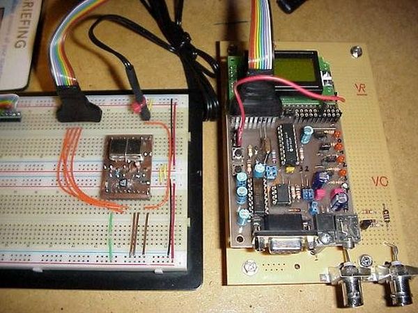
The AD9835 comes in a very smal TSSOP housing. So to start developing I needed a more bigger, better to handle form of the AD9835. I packed it with a 50 MHz osciliator module and some parts needed for propper operation on a small PCB with two connectors with standard pin sizes. This simplifies the development enormous. You now can use your standard breadboard to design systems with the AD9835.
After the hardware description you will find a code sample of a SSTV Testgenerator based on this module and a simple PIC 16F84. This shows that even uncommon digital modes can be done with a PIC. This Testgenerator produces a color bar screen using Martin-1 SSTV protocol and also sends the correct VIS code for Martin-1.
DISCLAIMER:
THIS CONTENT IS PROVIDED TO INTERESTED PEOPLE "AS IS" FOR NON COMERCIAL
PURPOSE ONLY. UNDER  NO CIRCUMSTANCES I AM RESPONSIBLE  FOR ANY DAMAGES
TO  YOUR RADIO, PC OR OTHER  EQUIPMENT. THIS  DEVICE  WAS TESTED  UNDER
DIFFERENT  CONDITIONS   AND  UNTIL  NOW  IT  WORKS   WITHOUT  PROBLEMS.
Schematics
This is the schematic of the AD9835 Module. It follows in some parts the schematic in the AD9835 reference manual. Other parts could be better. For example the power handling (Analog and Digital VDD and VSS) is not that optimal as it could be (just L1 to prevent some disturbances).

The PCB
The PCB is single sided and except the 50 MHz oscillator module and the coil which are of normal size all other components are SMD size 1206. Special care must be taken soldering the AD9835. It comes as a TSSOP and unless you don’t have a soldering iron with a very, very fine tip and a magnifying glass you wont get happy builing this project. Be warned! This chip is hard to solder.
The red marked lines on the PCB are simple jumper wires which must be soldered from the non copper side of the board. For more details see the pictures.
For more detail: A DDS Module based on the AD9835 using PIC16F84
- What is the purpose of this AD9835 module?
To provide a breadboard-friendly breakout of the AD9835 DDS so a PIC can generate better signals and save program memory. - Can this module be used with a PIC microcontroller?
Yes; the article demonstrates use with a PIC16F84 for an SSTV Testgenerator. - What oscillator frequency is used on the module?
A 50 MHz oscillator module is used. - Does the PCB use through-hole or SMD components?
The PCB is single-sided and most components are SMD 1206 size, except the oscillator and coil which are normal size. - Is soldering the AD9835 difficult?
Yes; the AD9835 is a TSSOP and is hard to solder without a very fine tip soldering iron and magnification. - Are there any special PCB jumpers required?
Yes; red marked lines on the PCB indicate jumper wires to be soldered from the non-copper side. - Does the schematic follow the AD9835 reference manual?
It follows parts of the AD9835 reference manual, though some areas like power handling are not optimal. - What example project is provided with the module?
An SSTV Testgenerator producing Martin-1 color bars and sending the VIS code is provided.
