
Summary of Knight Rider Light computer – version 2
This article describes a compact Knight Rider light computer based on the PIC12F629 microcontroller. It features an internal 4 MHz oscillator and reset circuit, eliminating the need for external components. The design uses eight LEDs driven by the PIC's I/O pins, powered by a 9V supply regulated down to 4.7V via a zener diode. The software, written in C using HI-TECH C and MPLab, cycles through six output states to create the light effect.
Parts used in the Knight Rider Light Computer:
- PIC12F629 microcontroller
- Eight LEDs
- Two resistors
- Zener diode D1
- Olimex USB PIC programmer
- HI-TECH C language compiler
- MPLab tool
This knight rider light computer is a successor of my first version of the Knight Rider. This version is much smaller and justifies the use of a microcontroller. The project is based on the PIC 12F629 microcontroller.
The hardware part
Unlike my previous project this light computer is build around the PIC12F629: a microcontroller with only 8 pins. It is shipped in a DIL-8 housing.
 An external clock is not necessary: the chip has an internal 4 MHz oscillator. The reset circuit is not necessary either: I configured the PIC to use its internal reset circuit. So only 2 pins are needed to power the microcontroller. All other pins are available for I/O.
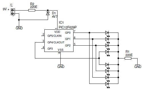
The schematic diagram can be kept very small. You only need the PIC12F629, eight LEDs, two resistors and a zenerdiode.
Each output of the PIC drives two LEDs. The cathode of all LEDs is common and connected to a single resistor. This is not a good design practice: each LED should have its own resistors as LEDs should never be placed in parallel. I did it anyway in this particular design because I needed a very compact solution (2 LEDs of the same type can slightly differ: they can have a different forward voltage. This can cause problems when they are placed in parallel).
The PIC’s GP03 port doesn’t drive any LEDs because it is solely an input port.
The circuit itself must be powered by a 9 VDC supply. This voltage is down sized to 4.7V by a zenerdiode D1 and resistor R2. Eventually they can be replaced by a 7805 regulator.
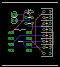
Possible PCB Layout
The image at the left illustrates how small this circuit could be when you create a PCB of it.Please note I drew this PCB very quick – I didn’t check it for errors as it is just an example. The PCB can’t be downloaded from this website.
 The software part
I wrote the software in the C language. I used the (free) HI-TECH C language that was included with MPLab, a tool for the PIC microprocessors.
I used an array that contains all the 6 different output states. A loop is cycled: each cycle another output state is retrieved from the array.
I programmed this microcontroller with my very cheap Olimex USB PIC programmer [External]. This programmer can be used with Microchip MPLab so you don’t need any additional software.
For more detail: Knight Rider Light computer – version 2
- What microcontroller is used in this project?
The project is based on the PIC12F629 microcontroller. - Does this design require an external clock?
No, the chip has an internal 4 MHz oscillator so no external clock is necessary. - How many pins does the PIC12F629 have?
The PIC12F629 is a microcontroller with only 8 pins. - What voltage is required to power the circuit?
The circuit must be powered by a 9 VDC supply. - Can the zener diode be replaced by another component?
Yes, the zener diode and resistor can eventually be replaced by a 7805 regulator. - Why are two LEDs connected in parallel per output?
This was done to achieve a very compact solution despite it not being good design practice. - Which programming language was used for the software?
The software was written in the C language using HI-TECH C. - What tool was used to program the microcontroller?
An Olimex USB PIC programmer was used to program the device.
