
Summary of Big 7-segment Digital Clock
This article describes building a digital LED clock using a PIC microcontroller and four large seven-segment displays. It outlines required parts, assembly steps (paper schematic, parts collection, soldering to vero board, enclosure construction), and programming the PIC with a provided HEX file. It notes optional 7805 regulator protection, advises using an IC socket for the PIC, and explains using common anode or common cathode displays.
Parts used in the Big 7-segment Digital Clock:
- 4x 6 inch seven-segment displays (common anode or common cathode)
- PIC16F84A or PIC16F628 microcontroller
- 3x 10K resistors
- 2x 22pF capacitors
- 4MHz crystal (XTAL)
- 2x tactile switches (micro switches) for hour and minute adjust
- Optional 7805 5V voltage regulator
- Vero board (dot matrix board) or PCB
- 18-pin IC base or ZIF socket
- Wiring and other seven-segment driver circuit parts as per schematic
- Enclosure materials (acrylic sheet, glue)
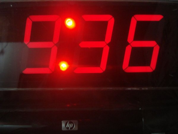
Using only 2 capacitors, 3 resistors, 4 BIG seven-segment Display, 1 xtal, 2 switches ,and 1 Microcontroller PIC, you can build this Digital Led Clock main circuit.
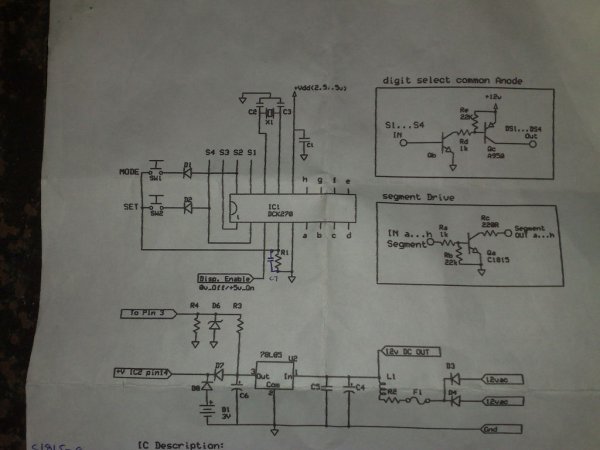
you can use common anode or common cathode display, just select the display type. Here is the pinout information:(I have attach the all diagrams of parts and 7 segments)
I’m used 4x 6″ big 7 segment display’s.
Step 1: Simple paper copy schematic
IC – PIC16F628 / PIC16F84A
Step 2: Collect your parts:

4x 6″ big 7 segment display
PIC16F84A
3x 10K Resistors
2x tack switches (micro switches)
4MHz Cristal (XTAL)
2x 22PF
If you are planing to protect your IC you should connect the IC through 5V regulator (1x 7805)
Vero baord(I used dot matrix board)
and other 7 Segment driver circuit parts displayed with attach image.
Step 3: Solder your all parts

Solder your all parts on to your vero board matching with this Circuit diagram.
Please do not solder your PIC16F84 on your board.Fix that through 18 pin IC base or Zif socket.
Step 4: Make your enclosure

and completed circuit board and 7segment board fix on your back plastic acrylic sheet.
and fix the Hour and Mins adjusting button to your enclosure right side panel.
Step 5: Programe Your PIC16F84

I have attach the HEX (16F84 clock) file for this clock.You have to burn it into your chip well.
Source : Big 7-segment Digital Clock
- Which PIC IC is used for this clock?
The article uses PIC16F84A or PIC16F628. - How many capacitors are required?
Two 22pF capacitors are required. - Can I use common anode or common cathode displays?
Yes, you can use common anode or common cathode displays; just select the display type. - What crystal frequency is used?
A 4MHz crystal (XTAL) is used. - How do I protect the PIC IC?
You can protect the PIC by powering it through a 5V regulator such as a 7805. - Should I solder the PIC directly to the board?
No, the article advises using an 18-pin IC base or ZIF socket instead of soldering the PIC directly. - What switches are used for time adjustment?
Two tactile micro switches are used for hour and minute adjusting buttons. - Is a HEX file provided for programming the PIC?
Yes, the article includes a 16F84 clock.hex file to burn into the chip.
