Summary of Analog to Digital Converter Using PIC16f877A Microcontroller – Beginners Guide using pic microcontoller
This article explains using the built-in ADC module of the PIC16F877A microcontroller to convert analog signals into 10-bit digital values, using MikroC Pro compiler and Proteus 8 for simulation. It covers ADC basics, the ADC-related registers, PORTA multiplexing with analog inputs, and MikroC ADC library routines, and includes a demonstration video and simulation to help program the PIC for ADC applications like digital voltmeters.
Parts used in the PIC16F877A ADC Project:
- PIC16F877A microcontroller
- MikroC Pro compiler (software)
- Proteus 8 simulator (software)
- Analog input source (sensor or signal generator)
- LCD module (for display)
- Power supply
- Connecting wires and breadboard or PCB
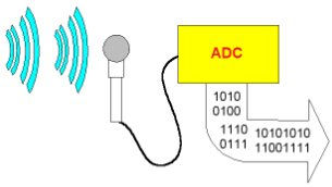
What is meant by Analog to Digital Converter (ADC)? An ADC converts analog signal to it’s corresponding digital signal.
How to convert analog signal to digital signal? CircuitsGallery.com has already posted ADC using LM324 IC, in that ADC tutorial I had already explained Analog to Digital Converter how it works.
 While dealing with Microcontrollers we may face many situations where we have to use ADCs (Digital voltmeter, ammeter etc.). In such situations it’s difficult to set up a separate ADC hardware circuit for our project.
So How to Use Analog to Digital Converter (ADC module) in PIC microchip microcontroller? PIC microcontrollers have inbuilt ADC module making easy Analog to Digital conversion.
In this article I’m gonna show you how to make use of ADC module in PIC16F877A microcontroller with the help of Mikro C Pro compiler and Proteus 8 simulator.
At the end of this tutorial, I did the video demonstration and simulation about analog to digital conversion using PIC16f877a.
After reading this ADC tutorial, I’m sure that you will be able to program a PIC microcontroller for manipulating the ADC module. Come on let’s start PIC microcontroller programming.
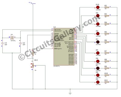
Before going to the circuit diagram and embedded program, let me figure out some details about ADC in PIC and also ADC and inbuilt library functions in Mikro C.
ADC Register in PIC MCU
- ADC (Analog to Digital Converter) module is offered in many of PIC MCU models.
- The Analog-to-Digital (A/D) Converter module has eight inputs for the 40 pin PIC Microcontrollers.
- In PIC16F877A, PORTA is multiplexed with ADC register, Comparator and Digital I/O operations. Due to the availability of ADC, PORTA is also known as Analog port.
- In order to work on ADC we must configure the ADC register in proper way.
- In PIC MCU, the conversion of an analog input signal effects in an equivalent 10-bit digital number (10 bit ADC).
Mikro C ADC Library and Important Library Routines for ADC Module
Micro C Library functions provide comfortable platform for working with ADC module in PIC. The only thing that we should add is the LCD library from the library manager.
For more detail: Analog to Digital Converter Using PIC16f877A Microcontroller
- What is meant by Analog to Digital Converter ADC?
An ADC converts an analog signal to its corresponding digital signal. - How to convert analog signal to digital signal using PIC16F877A?
Use the PIC16F877A built-in ADC module, configure ADC registers, and read the 10-bit digital result via code in MikroC Pro. - Why use the PIC16F877A ADC module instead of separate ADC hardware?
Because the PIC16F877A has an inbuilt ADC module which makes analog to digital conversion easier without separate ADC hardware. - Which port on PIC16F877A is used for analog inputs?
PORTA is multiplexed with ADC inputs and is known as the analog port. - What resolution does the PIC16F877A ADC provide?
The PIC16F877A ADC provides a 10-bit digital result. - What software tools are demonstrated for PIC16F877A ADC development?
The article demonstrates using MikroC Pro compiler and Proteus 8 simulator. - Do I need additional libraries to work with ADC in MikroC?
MikroC provides ADC library functions and you should also add the LCD library from the library manager if using an LCD. - What applications are mentioned that use ADCs with microcontrollers?
Digital voltmeter and ammeter are mentioned as examples where ADCs are used.