Summary of A development board for the ESP8266-03
Summary: This article describes a low-cost ESP8266 module-based development board for rapid IoT prototyping. It breaks out all ESP8266-03 IOs, adds a 3.3V LDO, USB-to-UART converter, supporting logic, and a button to trigger the bootloader. The board enables solder-free prototyping with an included breadboard and is designed to be cheaper and simpler than integrating individual RF components onto a custom PCB for small production runs.
Parts used in the ESP8266-03 Development Board:
- ESP8266-03 module
- 3.3V LDO regulator
- USB to UART converter
- Logic components (level shifters/logic as described)
- Bootloader trigger button
- Breadboard for prototyping
- Double sided tape (optional for mounting)
These modules come in different shapes and colours and can be purchased from the internet for 3 dollars only.
They are therefore cheap enough to enable many Internet of Things applications like monitoring your home temperature and activity all year round (if you ever need to do that).
And at this price, you’re actually better off directly soldering the complete board on your existing PCB rather than integrating each of its components, as it would result in a higher board cost (for less than 10k platforms produced) and possible RF related problems.
The ESP8266 modules come with a pre-loaded firmware that will accept some commands  through their UART interface (connect to wifi, open udp socket, send data to this IP…). Moreover, since Espressif recently released their SDK you can now load your own custom programs using the existing bootloader. To launch this bootloader you just have to connect some IOs to GND in a specific order.
However, anyone wanting to develop a project involving dozens of Wifi nodes has to start from somewhere, eg make a prototype of their future platform. That is why I developed this development board, so the prototyping stage is as simple as possible.
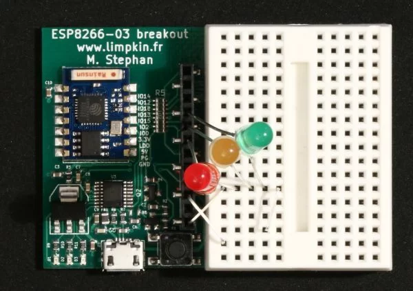
As you can see in the picture below the dev board breaks out all the ESP8266-03 IOs, includes a 3.3V LDO, a USB to UART converter, some logic and a button to automatically start the bootloader.
With the included breadboard solder free prototyping is therefore made possible!
You’ll notice that there aren’t any through hole components, so you may put double sided tape on the board’s back if you need to stick it somewhere. Have a look at the extremely simple schematics:
For more detail: A development board for the ESP8266-03
- What is the development board used for?
The board is used to simplify prototyping with the ESP8266-03 by breaking out IOs and providing power, USB-UART, and a bootloader button. - Can I program custom firmware on the ESP8266-03 using this board?
Yes, the board includes the necessary connections and a button to launch the existing bootloader so you can load custom programs. - Does the board include a power regulator?
Yes, the board includes a 3.3V LDO regulator. - Is a USB to UART converter included on the board?
Yes, a USB to UART converter is included to communicate with the ESP8266-03 over serial. - How does the board help with solder-free prototyping?
The board is supplied with a breadboard, enabling solder-free prototyping. - Are there through hole components on the board?
No, the article states there are no through hole components, allowing use of double sided tape for mounting. - Why use this dev board instead of integrating components on a custom PCB?
Because buying cheap prebuilt modules is cheaper and avoids RF problems and higher board cost for small production runs under 10k platforms. - Does the ESP8266 module come with preloaded firmware?
Yes, the ESP8266 modules come with pre-loaded firmware that accepts UART commands for WiFi and network operations.