
Summary of Simple PIC LC meter
This article details a DIY LC meter project using a PIC 16F628A microcontroller. The author adapted an existing schematic to use a 5V Sony mobile phone adapter instead of a 7805 regulator. Modifications included changing the trimmer potentiometer to 10k, upgrading specific capacitors to tantalum and higher values, and utilizing styroflex capacitors for precision. The device consumes 30mA with the backlight active and relies on an original PCB modified for the new components.
Parts used in the Simple PIC LC meter:
- PIC microcontroller 16F628A
- 5V adapter from Sony mobile phone
- 10k trimmer-potentiometer
- Three 10uF tantalum capacitors
- 1000uF capacitor (replacing C7)
- Two 1000pF styroflex 1% capacitors
- 82uH inductor
- LCD module with backlight
- Modified original PCB
Description
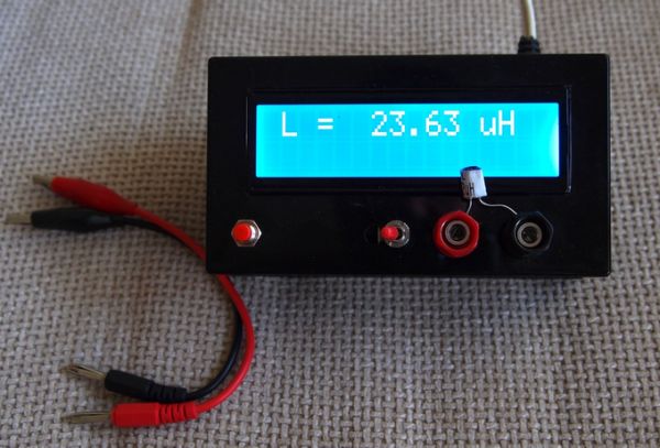
Here is another piece of laboratory equipment – LC meter. This type of meter, especially L meter is hard to find in cheap commercial multimeters.
Schematic of this one came from this web page: https://sites.google.com/site/vk3bhr/home/index2-html.
It uses PIC microcontroller 16F628A, and because I recently acquired a PIC programmer, I decided to test it with this project. Following the above link you will find the original schematic, PCB, source and HEX files for programing the microcontroller and detailed description.
Here is my adaptation of the schematic:
I removed the 7805 regulator, because I decided to use a 5V adapter from Sony mobile phone.
In the schematic, trimmer-potentiometer is 5k, but actually I put 10k, after consulting with the datasheet of the LCD module I bought. All three 10uF capacitors are tantalum and C7 – 100uF actually is 1000uF. Two 1000pF capacitors are styroflex 1% and inductor is 82uH. Total consumption (with back light) of the device is 30mA.
R11 limits the back light current and must be calculated according to the actual LCD module used.
I used the original PCB as a starting point and modified it to suit better to my components.
For more detail: Simple PIC LC meter
- What type of microcontroller is used in this LC meter?
The project uses a PIC microcontroller 16F628A. - Can I use a 7805 regulator for power?
No, the author removed the 7805 regulator and used a 5V adapter from a Sony mobile phone instead. - What value did the author choose for the trimmer-potentiometer?
The author used a 10k trimmer-potentiometer after consulting the LCD datasheet, despite the schematic suggesting 5k. - What type of capacitors are used for the three 10uF components?
All three 10uF capacitors are specified as tantalum. - Does the actual C7 capacitor value match the schematic?
No, while the schematic indicates 100uF, the author actually installed a 1000uF capacitor for C7. - What material are the two 1000pF capacitors made of?
The two 1000pF capacitors are styroflex with 1% tolerance. - How much current does the device consume with the backlight on?
The total consumption of the device with the backlight is 30mA. - What is the function of resistor R11?
R11 limits the back light current and must be calculated according to the actual LCD module used. - Did the author design a new PCB or modify an existing one?
The author used the original PCB as a starting point and modified it to suit their specific components.
