Summary of Morse Code Decoder
This article describes a Morse code decoder project that converts audio signals into digital data. It begins with an electret microphone and a transistor amplifier acting as a bandpass filter. The signal is then processed by an NE567 PLL tone detector to generate a dot-and-dash pattern. Finally, a PIC16F84 microcontroller interprets this data while an LED provides visual tuning feedback for the receiver.
Parts used in the Morse Code Decoder:
- Electret microphone
- Common emitter follower amplifier transistor
- Coupling capacitors
- Feedback capacitor
- NE567 PLL tone detector/decoder
- PIC16F84 microcontroller
- LED
Morse code is used in telecommunication; it is a method of transmitting and receiving coded information. Each character (letter or numeral) is coded/represented by a unique sequence of dots and dashes. Compared to voice, Morse code is less sensitive to poor signal conditions, yet still comprehensible to humans without a decoding device, therefore, a useful alternative to synthesized speech for sending automated data to skilled listeners (radio operator) on a voice channel.
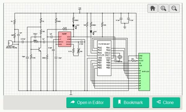
The project’s first part is composed of an electret microphone followed by a common emitter follower amplifier; this transistor amplifier also acts as a first level bandpass filter. Its band edges are determined by the size of the coupling capacitors, and the feedback capacitor between the transistor’s base and collector terminals. The next part of the project is the PLL (phase lock loop) tone detector/decoder NE567; its output is a one-zero pattern replicating the dots-and-dashes sequence of the received signal. This output drives both an input to the PIC16F84 microcontroller and an LED that is used as a receiver tuning aid.
For more detail: Morse Code Decoder
- What is Morse code used for?
Morse code is used in telecommunication to transmit and receive coded information using unique sequences of dots and dashes. - How does the first part of the project work?
The first part uses an electret microphone followed by a common emitter follower amplifier that acts as a first level bandpass filter. - What determines the band edges of the amplifier?
The band edges are determined by the size of the coupling capacitors and the feedback capacitor between the transistor terminals. - Which component detects the tone in the second part?
The NE567 phase lock loop (PLL) tone detector decodes the received signal. - What does the output of the NE567 drive?
The output drives both an input to the PIC16F84 microcontroller and an LED used as a receiver tuning aid. - Can Morse code be understood without a decoding device?
Yes, Morse code is comprehensible to humans without a decoding device if they are skilled listeners like radio operators. - Why is Morse code useful compared to voice?
Morse code is less sensitive to poor signal conditions yet still comprehensible to humans on a voice channel. - What sequence does the NE567 output replicate?
The output replicates the one-zero pattern of the dots-and-dashes sequence of the received signal.