Summary of USB:- DC Motor Controller using PIC18F4550 (keyboard)
This project uses a PIC18F4550 USB interface board and a C# HID application to control a DC motor via keyboard. The PIC outputs drive an L293D motor driver; motor supply is regulated with a 7805 linear regulator. Schematics are provided as images and Eagle files; single-motor wiring is shown though dual-motor control is possible.
Parts used in the USB DC Motor Controller using PIC18f4550 (keyboard):
- PIC18F4550 USB interface board (USB DEMO interface Board)
- Computer with C# HID application (keyboard control)
- L293D motor driver IC
- DC motor
- 7805 linear voltage regulator IC
- Power supply for motor (voltage source)
- Connecting wires and prototyping hardware
- Schematic files (image and EAGLE SCH file)
- USB:- DC Motor Controller using PIC18f4550 (keyboard)
Hello friends,
Requirements
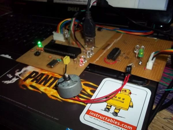
A small application [C#] is controlling my pic18f4550 USB interface board with my computer, enabling me to control my board with keyboard. The output of the microcontroller is given to the input of a L293D motor driver , hence enabling me to control my DC motor in ( forward / reverse ) that is Clockwise and Counter Clockwise | anti-clock (cw/ccw) direction.If you really interested in robotics and controlling stuffs then one of the most basic thing is to control your own applications like DC Motors , Stepper Motor , Servo (with pwm) etc etc. So lets do it with kind of absolute beginner level with DC motors.
IF you are really beginner then i suggest watch all the three videos.
The USB Device project I have already done before here http://www.instructables.com/id/USB-Project-USB-Interface-Board-Using-PIC18F455/ you can download the C# application [ pic18f4550 board tutorial ] from the link.This demo board enables to use Keyboard. this l293d motor Driver is just a application of the USB Interface board.
The input voltage for the motor is coltrolled with a Linear Voltage Regulator IC 7805, For 5v input voltage to the motors.
The working of the this project is very simple
USB + C# [HID] > pic18f4550 > L293D > DC motor
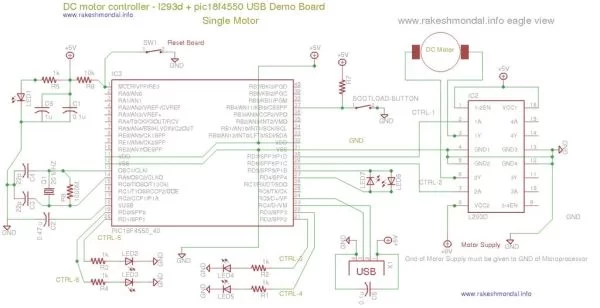
Schematic for USB Motor Driver
You can find the Schematic for this USB DC motor controller in the pictures here. Its a Single DC motor interface to pic18f4550 however two two interface is possible.
-Schematic As EAGLE SCH file.
WORKING OF THE L293D MOTOR Driver
ABOUT L293D
You can find the pin diagram of l293d motor driver with a short google, the chip is kind of self explanatory when you see it. With one single chip you can control two D.C motors to rotate in forward/ reverse direction on your command.
For more detail: USB:- DC Motor Controller using PIC18F4550 (keyboard)
- How is the DC motor controlled in this project?
The motor is controlled via a C# HID application on a computer sending commands over USB to the PIC18F4550, whose outputs drive the L293D motor driver to control motor direction. - Can this setup control motor direction both forward and reverse?
Yes, the L293D motor driver enables control of the DC motor to rotate in forward and reverse directions. - What role does the 7805 linear regulator play?
The 7805 linear regulator provides a regulated 5V input voltage for the motor control circuitry. - Is there a schematic available for the USB motor driver?
Yes, schematics are provided as image files and as an EAGLE SCH file. - Can the PIC18F4550 interface control more than one motor?
The provided schematic shows a single DC motor interface, but two motor interfaces are possible with the L293D. - Where can I get the C# application for the PIC18F4550 board?
The C# pic18f4550 board tutorial and application are available from the linked USB Project USB Interface Board using PIC18F455 instructable. - What is the overall signal flow in the project?
The flow is Computer with C# HID and keyboard input > PIC18F4550 USB interface board > L293D motor driver > DC motor.