Summary of How to take input with PIC18F4550 Microcontroller
This article explains how to configure input and output operations on a PIC18F4550 microcontroller. It details setting TRIS registers to define pins as inputs or outputs, using PortD examples. The project demonstrates controlling an LED on pin RA0 based on the state of a tactile switch connected to pin RA5, providing source code and configuration steps for digital I/O handling.
Parts used in the PIC18F4550 Input Control Project:
- LED
- PIC18F4550
- Tactile Switch
Any microcontroller based system typically has an input and a corresponding output. Taking simple output with a PIC microcontroller has been explained in LED blinking with PIC18F4550. This article explains how to provide an input to the controller and get a corresponding output using PIC18F4550.
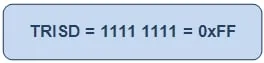
PIC18F4550 has a total of 35 I/O (input-output) pins which are distributed among 5 Ports. Each Port of a PIC microcontroller corresponds to three 8-bit registers (TRIS, PORT & LAT) which should be configured to use the Port for general I/O purpose. For more details, refer LED blinking using PIC.
|
TRISD
|
Bit 7
|
Bit 6
|
Bit 5
|
Bit 4
|
Bit 3
|
Bit 2
|
Bit 1
|
Bit 0
|
|
Value
|
1
|
1
|
1
|
1
|
1
|
1
|
1
|
1
|
|
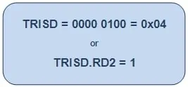
TRISD
|
Bit 7
|
Bit 6
|
Bit 5
|
Bit 4
|
Bit 3
|
Bit 2
|
Bit 1
|
Bit 0
|
|
Value
|
–
|
–
|
–
|
–
|
–
|
1
|
–
|
–
|
|
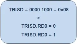
TRISD
|
Bit 7
|
Bit 6
|
Bit 5
|
Bit 4
|
Bit 3
|
Bit 2
|
Bit 1
|
Bit 0
|
|
Value
|
–
|
–
|
–
|
–
|
1
|
–
|
–
|
0
|
Project Source Code
###
// Program to control an LED using a switch
// Configuration bits
/* _CPUDIV_OSC1_PLL2_1L, // Divide clock by 2
_FOSC_HS_1H, // Select High Speed (HS) oscillator
_WDT_OFF_2H, // Watchdog Timer off
MCLRE_ON_3H // Master Clear on
*/
void main()
{
ADCON1=0x0F; // Set all pins as digital I/O
CMCON=0x07; // Set all comparators as digital I/O
TRISA.RA0=0; // Configure pin RA0 as output
TRISA.RA5=1; // Configure pin RA5 as input
while(1)
{
if(PORTA.RA5) // If input is high
LATA.LATA0=1; // Turn the LED On
else
LATA.LATA0=0; // Turn the LED Off
}
}
###
Project Components
Project Video
Source: How to take input with PIC18F4550 Microcontroller
- How many I/O pins does the PIC18F4550 have?
The PIC18F4550 has a total of 35 I/O pins distributed among 5 Ports. - What value should be set in the TRIS register to configure a pin as input?
To configure a particular port or pin as input, the corresponding TRIS register bit should be set to high (1). - What value should be set in the TRIS register to configure a pin as output?
To configure a pin as output, the relevant TRIS register or bit should be set to low (0). - Which pin is used for the input switch in this project?
A tactile switch is connected on pin RA5 of PortA to provide input to the microcontroller. - Which pin is used for the LED output in this project?
The output is monitored on an LED connected to pin RA0. - How are comparators configured in the provided source code?
The CMCON register is set to 0x07 to set all comparators as digital I/O. - What command sets all pins as digital I/O in the code?
The command ADCON1=0x0F sets all pins as digital I/O. - What happens when the input at RA5 is high?
If the input at PORTA.RA5 is high, the code turns the LED on by setting LATA.LATA0 to 1.