Summary of Digital Voltmeter using PIC16F877a
This article details a digital voltmeter project using the PIC16F877A microcontroller to measure voltages from 0 to 20V. The system utilizes the microcontroller's internal 10-bit ADC on channel AN2 to convert analog signals, which are scaled down via a resistor divider and protected by a Zener diode. The converted values are processed in MikroC software and displayed on a 16x4 HD44780 LCD within the Proteus ISIS simulation environment.
Parts used in the Digital Voltmeter:
- PIC16F877A Microcontroller
- Liquid Crystal Display 16x4 HD44780
- Resistor Divider Network
- 5.1V Zener Diode
- Variable Resistor (RV3)
- 8 MHz Crystal Oscillator
This is a simple project showing you how to make a digital voltmeter of range 0-20V using microcontroller PIC16F877A and a Liquid Crystal Display 16×4 HD44780 LCD in Proteus ISIS.
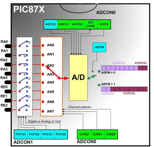
The microcontroller PIC 16F877A has 8 analog input channels for the in-built 10-bit ADC. In this project AN2 channel of pic16F877A microcontroller is used. ADC module of pic microcontroller converts analog signal into binary numbers. PIC16F877A microcontroller have 10 bit ADC. So it converts analog signal to 10 bit digital number which can be back converted into voltage and displayed on LCD.
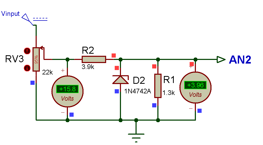
ou cannot feed 20V directly to a PIC I/O pin, you need a resistor divider network that converts 0-20V range into 0-5 V. A 5.1V Zener diode in the figure is to prevent V3 (V in) to rise above 5.1V if the input voltage goes much above 20V. This will protect the microcontroller.
PIC16F877A microcontroller built in ADC (analog to digital converter) is used to measure analog voltage. The analog to digital conversion isdone by the PIC ADC module. In the code, I’ve used the mikro C library function for ADC. You can view the library file in this link
Code Designing in MikroC Pro For PIC :
So, here’s the programming code you need to use for Displaying voltage value on LCD using PIC Microcontroller in Proteus ISIS:
/*

* Project name:

Digital Voltmeter  (Voltage measurement)

* Copyright:

(c) LET'S THINk BINARY, 2017.

* Revision History:

V0.0

* Description:

This digital voltmeter using PIC16F877A  can read voltage only between 0-20 volt.

Voltage is displayed on LCD.

* Test configuration:

MCU:             PIC16f877a

Oscillator:      8.0000 MHz Crystal

SW:              mikroC PRO for PIC

http://www.mikroe.com/mikroc/pic/

* NOTES:

-  This Our Group (thanks to join and participate) :

https://www.facebook.com/groups/816450708460518/

-  Facebook page (thanks to like and share) :

https://www.facebook.com/Lets-Think-Binary-1728910547340654/

-  Youtube Channel (thanks to subscribe) :

https://www.youtube.com/channel/UCTIAzxEkyeA6HTvl_VHd-Tw

*/

// LCD module connections

sbit LCD_RS at RB4_bit;

sbit LCD_EN at RB5_bit;

sbit LCD_D4 at RB0_bit;

sbit LCD_D5 at RB1_bit;

sbit LCD_D6 at RB2_bit;

sbit LCD_D7 at RB3_bit;

sbit LCD_RS_Direction at TRISB4_bit;

sbit LCD_EN_Direction at TRISB5_bit;

sbit LCD_D4_Direction at TRISB0_bit;

sbit LCD_D5_Direction at TRISB1_bit;

sbit LCD_D6_Direction at TRISB2_bit;

sbit LCD_D7_Direction at TRISB3_bit;

// End LCD module connections

char *text;

unsigned int v,vp;

char *volt = "00.00 VOLTS";

//char *volt = "00.000 VOLTS";  // format 00.000

void main()

{

CMCON = 0x07;                     // Comparators OFF

TRISA = 0x04;                     // Configure RA2 as Inpu

ADCON1 = 0x80;                    //  Configure  PORTA & PORTE as analog

Lcd_Init();                       // LCD display initialization

Lcd_Cmd(_LCD_CURSOR_OFF);         // LCD command (cursor off)

Lcd_Cmd(_LCD_CLEAR);              // LCD command (clear LCD)

text = "LET'S THINK BINARY";      // Define the first message

Lcd_Out(1,2,text);                // Write the first message in the first line

text = "www.electronify.org";     // Define the second message

Lcd_Out(2,1,text);                // Write the  message in the second line

text = "DIGITAL Voltmeter";       // Define the third message

Lcd_Out(3,2,text);                //Write the  message in the third line

do

{

v = ADC_Read(2);                   // Read analog value from channel 2

v = ((v*4.89)/5)*20;               // V GOES FROM 0 TO 20 volts

// Resolution 10 bits  ( 0......1023)

if(v!=vp )

vp = v;

volt[0] = (v/10000)+ 48;         // Extract volts (thousands of millivolts) from result

// Write result in ASCII format

volt[1] = (v/1000)%10+48;        //  Extract thousands of mv

volt[3] = (v/100)%10+48;         // Extract hundreds of mv

volt[4] = (v/10)%10+48;          // Extract tens of millivolts if you want the format 00.000

Lcd_Out(4,1,"Voltage= ");

Lcd_Out(4,9,volt);

Delay_ms(200);

} while(1);

}
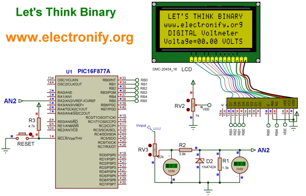
Digital Voltmeter using PIC16F877a (Schematic Diagram)
Results :
Compile the PIC code and generate the hex file from it. For simulating with PROTEUS ISIS hit run button and then you will get above output.
So, now we can see the LCD is displaying exactly the same values as are shown in the voltmeter. Now if you change the value of variable resistor RV3 then the value of voltage will change in LCD.
This digital voltmeter using PIC16F877A can read voltage only between 0-20 volt.
Resource :
You can download the MikroC Source Code and Proteus files etc from this link :
zip file of complete project digital voltmeter using pic16f677A
This Our Group (thanks to join and participate) :this link
Facebook page : this link
Youtube Channel (thanks to subscribe) : this link
For another similar project visit here: Digital Voltmeter using PIC16F877a
- What voltage range can this digital voltmeter measure?
The device is designed to read voltage only between 0 and 20 volts. - How does the system protect the microcontroller from high input voltage?
A 5.1V Zener diode prevents the input voltage from rising above 5.1V if it exceeds 20V. - Which specific pin is used for the analog signal input?
The AN2 channel of the PIC16F877A microcontroller is used for the analog input. - Can I feed 20V directly to a PIC I/O pin?
No, you cannot feed 20V directly; a resistor divider network must convert the range to 0-5V first. - What resolution does the built-in ADC provide?
The PIC16F877A has a 10-bit ADC that converts analog signals into 10-bit digital numbers. - Which software library is used for ADC functions in the code?
The mikro C library function for ADC is utilized in the programming code. - What happens if you change the value of variable resistor RV3?
Changing RV3 changes the voltage value displayed on the LCD. - How many analog input channels does the PIC16F877A have?
The microcontroller features 8 analog input channels for its in-built 10-bit ADC.