Summary of Double sensor interface Indoor/OutdoorThermometer using PIC16F877A Microcontroller
This project demonstrates reading two LM35 temperature sensors using a PIC16F877A microcontroller and displaying the data on a 4x20 LCD via Proteus ISIS. The system utilizes the microcontroller's built-in ADC to convert analog voltage from the sensors into digital values, which are then processed and shown as indoor and outdoor temperatures.
Parts used in Double sensor interface Indoor/OutdoorThermometer:
- PIC16F877A Microcontroller
- LM35 Temperature Sensor (Two units)
- LCD 4x20 Display
- 8.0000 MHz Crystal Oscillator
- MikroC PRO for PIC Software Library
- Proteus ISIS Simulation Environment
This is a simple project showing you how to read LM35 analog temperature sensor using a PIC microcontroller and LCD 4×20 in Proteus ISIS. In this tutorial we will make a practical use of the ADC. We will use them to show current temperature using two LM35 temperature sensors.
The temperature sensors are connected to the ADC ports of the microcontroller, which takes in the analog signal and gives out digital values across specified ports.
Across the defined output port of the microcontroller, LCD 4×20 is connected with takes the values of the temperature sensors (Indoor / Outdoor) and displays them.
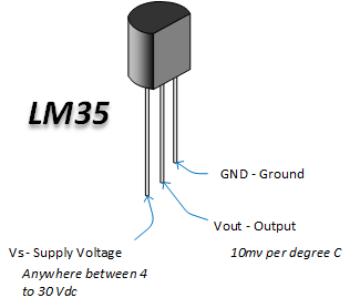
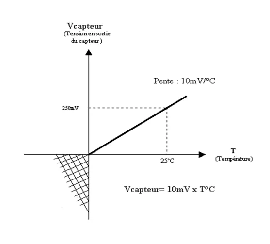
LM35 is a Three-Pins (Vcc,Output,GND) high precision temperature sensor having a resolution of 10mV/C starting at 0V (i.e. an output of 0V represents a temperature of 0C).
So :
10mV —> 1C
20mV —> 2C
500mV —> 50C and so on
ADC is an electronic circuit that converts continuous signals to discrete digital numbers. PIC16F877A microcontroller built in ADC (analog to digital converter) is used to measure analog voltage. The analog to digital conversion is done by the PIC ADC module. In the code, I’ve used the mikro C library function for ADC.
ADC Library provides you a comfortable work with the module.
Library Routines
- ADC_Init
- ADC_Get_Sample
- ADC_Read
ADC_Init
| Prototype | voidADC_Init(); |
| Returns | Nothing. |
| Description | This routine initializes PIC’s internal ADC module to work with RC clock. Clock determines the time period necessary for performing AD conversion (min 12TAD). |
| Requires |
|
| Example | ADC_Init(); // Initialize ADC module with default settings |
ADC_Get_Sample
| Prototype | unsigned ADC_Get_Sample(unsigned short channel); |
| Returns | 10 or 12-bit unsigned value read from the specified channel (MCU dependent). |
| Description | The function acquires analog value from the specified channel. Parameter channel represents the channel from which the analog value is to be acquired. Refer to the appropriate datasheet for channel-to-pin mapping. Note : This function doesn’t work with the external voltage reference source, only with the internal voltage reference. |
| Requires |
|
| Example | unsigned adc_value;…
adc_value = ADC_Get_Sample(2); // read analog value from ADC module channel 2 |
ADC_Read
| Prototype | unsigned ADC_Read(unsigned short channel); |
| Returns | 10 or 12-bit unsigned value read from the specified channel (MCU dependent). |
| Description | Initializes PIC’s internal ADC module to workwith RC clock. Clock determines the time period necessary for performing AD conversion (min 12TAD). Parameter channel represents the channel from which the analog value is to be acquired. Refer to the appropriate datasheet for channel-to-pin mapping. Note : This function doesn’t work with the external voltage reference source, only with the internal voltage reference. |
| Requires |
|
| Example | unsigned tmp;…
tmp = ADC_Read(2); // Read analog value from channel 2 |
You can view the library from this link
Double sensor interface Indoor/OutdoorThermometer using PIC16F877A Microcontroller (Code)
/*

* Project name:

LM35 Sensor (Temperature measurement)

* Copyright:

(c) lET'S THINk BINARY, 2017.

* Revision History:

V0.0

* Description:

A simple example of using the LM35 sensor.

Temperature is displayed on LCD.

* Test configuration:

MCU:             PIC16f877a

Oscillator:      8.0000 MHz Crystal

SW:              mikroC PRO for PIC

http://www.mikroe.com/mikroc/pic/

* NOTES:

-  This Our Group (thanks to join and participate) :

https://www.facebook.com/groups/816450708460518/

-  Facebook page (thanks to like and share) :

https://www.facebook.com/Lets-Think-Binary-1728910547340654/

-  Youtube Channel (thanks to subscribe) :

https://www.youtube.com/channel/UCTIAzxEkyeA6HTvl_VHd-Tw

*/

// LCD module connections

sbit LCD_RS at RB4_bit;

sbit LCD_EN at RB5_bit;

sbit LCD_D4 at RB0_bit;

sbit LCD_D5 at RB1_bit;

sbit LCD_D6 at RB2_bit;

sbit LCD_D7 at RB3_bit;

sbit LCD_RS_Direction at TRISB4_bit;

sbit LCD_EN_Direction at TRISB5_bit;

sbit LCD_D4_Direction at TRISB0_bit;

sbit LCD_D5_Direction at TRISB1_bit;

sbit LCD_D6_Direction at TRISB2_bit;

sbit LCD_D7_Direction at TRISB3_bit;

// End LCD module connections

unsigned int temp_res = 0;

float temp;

char txt[15];

char *text;

void display_sensor1(){

temp_res = ADC_Get_Sample(2);       // Get 10-bit results of AD conversion

temp = (temp_res * 5)/10.240;       // Calculate temperature in Celsuis

FloatToStr(temp, txt);              // Convert temperature to string

txt[5] = 0;

Lcd_Out(3,14,txt);                  // Write string in second row

Lcd_Chr(3,19,223);                  // Different LCD displays have different                                       // char code for degree 178 (in practice) or 223 (for proteus simulation)

Lcd_Chr(3,20,'C');                  // Display "C" for Celsius

}

void display_sensor2(){

temp_res = ADC_Get_Sample(6);       // Get 10-bit results of AD conversion

temp=(temp_res * 5000.0/1023.0 )/10;  // Calculate temperature in Celsuis

FloatToStr(temp, txt);              // Convert temperature to string

txt[5] = 0;

Lcd_Out(4,14,txt);                  // Write string in second row

Lcd_Chr(4,19,223);                  // Different LCD displays have different                                       // char code for degree 178 (in practice) or 223 (for proteus simulation)

Lcd_Chr(4,20,'C');                  // Display "C" for Celsius

}

void main()

{

CMCON = 0x07;                     // Comparators OFF

ADCON1 = 0x80;                    //  Configure  PORTA & PORTE as analog

TRISA = 0x04;                     // Configure RA2 pin as input

TRISE1_bit = 1;                   // Configure RE1 pin as input

ADC_Init();                       // Initialize ADC

Lcd_Init();                       // LCD display initialization

Lcd_Cmd(_LCD_CURSOR_OFF);         // LCD command (cursor off)

Lcd_Cmd(_LCD_CLEAR);              // LCD command (clear LCD)

text = "LET'S THINK BINARY";      // Define the first message

Lcd_Out(1,2,text);                // Write the first message in the first line

text = "www.electronify.org";     // Define the second message

Lcd_Out(2,1,text);                // Write the  message in the second line

Lcd_Out(3,1,"Temp_Sensor1:");

Lcd_Out(4,1,"Temp_Sensor2:");

//temp_res = 0;

do

{

display_sensor1();           // Dosplay thr tempedrature of sensor1

display_sensor2();           // Dosplay thr tempedrature of sensor2

Delay_ms(1000);

} while(1);

}
Double sensor interface Indoor/OutdoorThermometer using PIC16F877A Microcontroller (Schematic Diagram)
RESULTS :
Compile the PIC code and generate the HEX file from it. For the simulation with Proteus ISIS hit run button and then you will get above output.
So ,now we can see the LCD is displaying the Indoor and the Out door temperature. Now if you change the value of the two sensors then the value of temperature will change in LCD.
Resource :
You can download the MikroC Source Code and Proteus files etc from this link
This Our Group (thanks to join and participate) : https://www.facebook.com/groups/816450708460518/
Facebook page (thanks to like and share) :
https://www.facebook.com/Lets-Think-Binary-1728910547340654/
Youtube Channel (thanks to subscribe) :
https://www.youtube.com/channel/UCTIAzxEkyeA6HTvl_VHd-Tw
- How does the LM35 sensor output relate to temperature?
The sensor outputs 10mV per degree Celsius, meaning 0V represents 0C. - What function initializes the ADC module in the code?
The ADC_Init() routine initializes the internal ADC module to work with the RC clock. - Which pins are configured as inputs for the sensors?
RA2 pin is configured as input for sensor 1 and RE1 pin is configured as input for sensor 2. - How is the analog voltage converted to a temperature value?
The code multiplies the ADC sample result by 5 or 5000 and divides by 10.240 or 1023 to calculate Celsius. - Can this system display both indoor and outdoor temperatures simultaneously?
Yes, the LCD displays readings from two separate LM35 sensors labeled Temp_Sensor1 and Temp_Sensor2. - What software library is used for ADC operations?
The MikroC library functions ADC_Get_Sample and ADC_Read are used to acquire analog values. - Does the ADC function support external voltage references?
No, the library functions do not work with an external voltage reference source and only use the internal one. - What happens if you change the sensor values during simulation?
The temperature displayed on the LCD updates to reflect the new sensor values.