Summary of PIC18 Pulse Width Modulation (PWM) DC Motor Speed Controller with the RPM Counter Project
This tutorial demonstrates using a PIC18F14K50 in pulse steering ECCP mode to drive a DC motor and measure RPM, displaying speed and PWM duty on a 2×16 LCD. It combines PWM generation, ADC-based trimpot speed control, an IR reflective RPM sensor, external interrupt and 16-bit Timer0 for counting, and uses PICJazz 20-pin board with MPLAB and HI-TECH C tools.
Parts used in the PWM and RPM Counter Project:
- Microchip PIC18F14K50 microcontroller
- PICJazz 20PIN development board
- HD44780U 2×16 LCD (driven in 4-bit mode)
- DC Motor from dual shock PS2 PlayStation joystick
- Tamiya racing car tire
- Infrared reflective object sensor (RPM sensor)
- Trimpot (for adjusting motor speed via ADC)
- Wiring, connectors, and prototyping hardware
- Power supply suitable for the DC motor and MCU
- Microchip MPLAB IDE version 8.40
- HI-TECH C PRO PIC18 MCU Family Version 9.63PL3
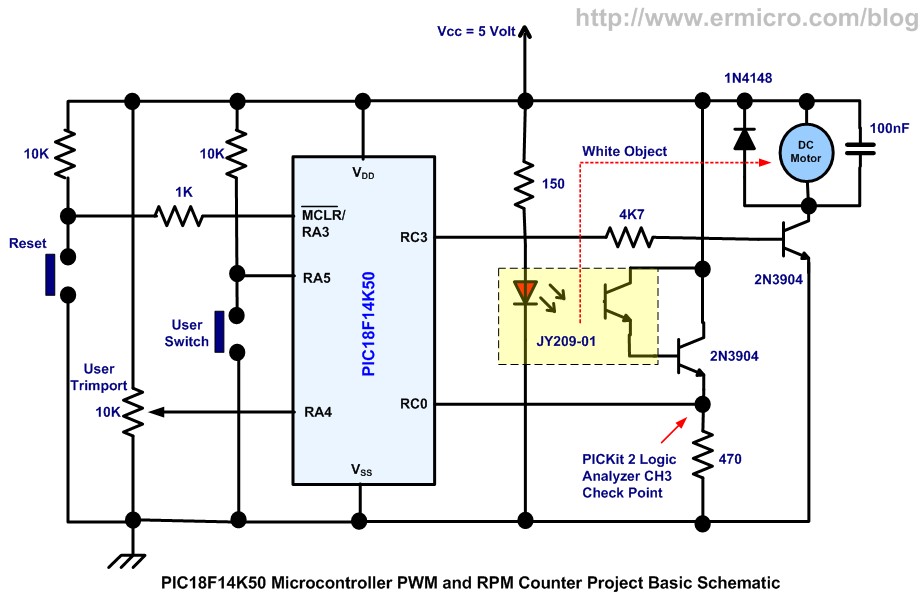
Equipped with sophisticated Enhanced Capture/Compare/PWM (ECCP) peripheral the Microchip PIC18F14K50 microcontroller could produce up to four PWM channels output. The enhanced PWM (Pulse Width Modulation) mode in ECCP peripheral is capable to drive the full bridge DC Motor circuit directly both in forward or reverse direction. It also could generate single PWM output on the selectable PIC18F14K50 pins when it configured in pulse steering mode. In this tutorial we will take advantage of PIC18F14K50 pulse steering mode to drive the DC Motor and at the same time we will build the RPM (Rotation per Minute) counter to observe the PWM effect on the DC Motor speed and display it on the 2×16 LCD.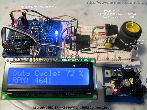
The PWM and RPM Counter Project
On this project we will use the HITEC C PRO PIC18 MCU Family Version 9.63PL3 and Microchip MPLAB IDE version 8.40 as our development tools platform. This project also serves as the learning tools of how to use many of the Microchip PIC18 advanced peripherals simultaneously to accomplish the project goal. You could see the complete project demonstrated on the video at the end of this tutorial; Ok now let’s list down all the project interesting features:
- Using Advanced 8-bit Microchip PIC18F14K50 microcontroller with PICJazz 20PIN development board
- Driving the HD44780U 2×16 LCD in 4-bit data mode
- Use DC Motor taken from discarded dual shock PS2 Playstation joystick and the Tamiya racing car tire for measuring the DC Motor RPM
- Simple and easy to build RPM sensor with the infra red reflective object sensor
- Use the ADC peripheral to read the trimport value for adjusting the DC Motor Speed and display the PWM duty cycle on the LCD
- Use the PIC18F14K50 external interrupt and 16-bit TIMER0 counter to measure the RPM and display it on the LCD.
For more detail: PIC18 Pulse Width Modulation (PWM) DC Motor Speed Controller with the RPM Counter Project
- What microcontroller is used in this project?
The PIC18F14K50 microcontroller is used in this project. - How many PWM channels can the PIC18F14K50 produce?
The PIC18F14K50 with its ECCP peripheral can produce up to four PWM channels. - Can the ECCP enhanced PWM mode drive a full bridge DC motor directly?
Yes, the enhanced PWM mode in the ECCP peripheral can drive a full bridge DC Motor circuit in forward or reverse. - How is a single PWM output generated on selectable pins?
Single PWM output can be generated on selectable PIC18F14K50 pins by configuring ECCP in pulse steering mode. - What toolchain is used to develop the project code?
The project uses HI-TECH C PRO PIC18 MCU Family Version 9.63PL3 and Microchip MPLAB IDE version 8.40. - How is the DC motor speed adjusted and displayed?
The ADC peripheral reads a trimpot value to adjust the DC motor speed and the PWM duty cycle is displayed on the LCD. - How is RPM measured in this project?
RPM is measured using an infrared reflective object sensor, the PIC18F14K50 external interrupt, and the 16-bit TIMER0 counter. - What display is used to show RPM and duty cycle?
An HD44780U 2×16 LCD driven in 4-bit data mode displays RPM and PWM duty cycle. - What motor and mechanical part are used for RPM measurement?
The motor is from a dual shock PS2 joystick and a Tamiya racing car tire is used for measuring RPM.