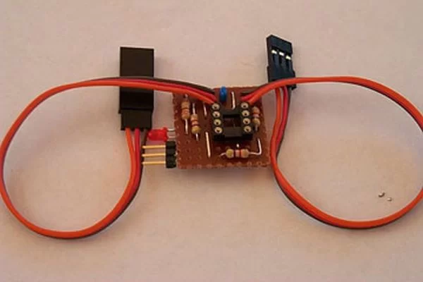
This document describes the complete design for a camera switch that uses a servo to activate the shutter. This page include links to the complete circuit diagram, the .HEX file required to program the 12F675, and complete construction details.
The switch consists of a PIC and a small number of standard components. The Servo Camera Switch connects inline between the receiver and the servo and manages the operation of the servo.
Important Note: there is a related design for direct shutter control for the Aiptek/Jazz cameras. This document is the base document for direct shutter control design, with the variations between the two designs explained elsewhere.
BackgroundThere are a number of options for trigger a camera for AP work:
- The camera can be triggered using an electronic switch circuit connected between the camera’s internal circuits and the receiver.
- The camera can be triggered using a servo connected to the radio control receiver. Some form of arm or other mechanism pushes the shutter button.
- The camera can be set to ‘auto’ shoot, just taking a photo every preset number of seconds.
For users of electronic switch circuits there are a number of designs available that each incorporate various features to manage various cameras. One of the key features in some switches is the ability to take a photo every now and again automatically so as to keep the camera from turning itself off.
This servo camera switch is aimed at providing features similar to some of the electronic switches for situations where a servo is used to trigger the shutter.
What this Servo Switch offersThis servo switch offers the following features:
- Threshold switching.
- Automatically takes a photograph to keep camera powered on.
- Automatic picture taking stops on loss of signal.
- Automatic picture taking stops on command.
- Operates in both still photo mode and video mode.
- Operates with cameras that require ‘focus’ time.
- User configurable parameters.
Threshold switchRather than the output servo tracking the input servo command position the servo switch positions the output servo in the idle position until the input servo command reaches the trigger position and then the servo switch commences to take a picture. After taking a picture the servo switch will wait for the input servo command to return to the ‘no shutter’ position before taking another picture.
The picture taking sequence involves moving the output servo to the focus position for the focus time, then the shutter position for the shutter time and finally back to the idle position for the post shutter time.Automatically takes a photographThe servo switch monitors the picture taking activity and will automatically take a photograph after a period of inactivity to ensure that the camera stays powered on.Automatic picture taking stops on loss of signalWhen the servo switch detects loss of input servo commands the switch stops automatically taking photos and this permits the camera to power off. The servo switch continues to produce output servo pulses to hold the servo in the ‘idle’ position.
The switch will start automatically taking pictures again if a manual picture request occurs after LOS.Automatic picture taking stops on commandWith some cameras it is desirable to permit the camera to automatically power off prior to landing. When the camera powers off the camera retracts its lens and close the lens cover.
The switch permits the automatic picture taking to be stopped by holding the input servo command in a particular position for a set time. Automatic ‘keep-alive’ will reactivate if a manual picture request is received.
For example, if the camera automatically powers off after 60 seconds without a picture being taken then 1 minute before you plan to land this facility is used to stop the automatic picture taking facility. Then the camera will power off automatically and retract the lens.
For users who are controlling the camera with a gear channel the power off position can be the same as the camera shutter position. In this situation a short press of the shutter will take a picture, a long press will take a picture and then command the switch to turn off the keep-alive function. The camera will then power down after its normal timeout.
Note: When shooting in video mode with the power off position the same as the shutter position you should command the power off at the end of a video sequence, otherwise the power off will start a new video segment and the camera won’t power off until its memory is full.Still photo and Video modeThe servo switch will operate in either still photo or video mode. In video mode the servo switch monitors the ‘capturing’ status and correctly operates the keep-alive function only when the camera is not in capture mode.Cameras that require focusing timeThe servo switch can be configured to move the output servo to a ‘focus’ position for some time prior to the servo moving to the ‘shutter’ position. This permits the switch to be used with cameras that require a period of time for focusing prior to the picture being taken.User configurable parametersThe servo switch contains a number of parameters that are programmed by the user, in a similar manner to modern ESCs. The parameters that are programmed include:
- Servo position for ‘idle’.
- Servo position for ‘focus’.
- Servo position to ‘shutter’.
- Length of time to position servo in ‘focus’ position.
- Length of time to position servo in ‘shutter’ position.
- Post shutter delay.
- ‘Keep-alive’ timeout.
- Input stick position for no shutter trigger.
- Input stick position for shutter trigger.
- Input stick position to disable the keep-alive timeout.
- Length of time the input position must be in disable position to disable keep-alive.
The switch comes with an initial set of parameters configured into the switch. These initial parameters are documented in the programming information below and permit the switch to perform basic functions without significant programming.
Operational OverviewOn power up the servo switch recalls the saved configuration information. If there is an error detected in this saved information and programming mode is not selected the switch will halt and flash the details of which information is not correctly programmed.
The switch computes the threshold input position, this is half way between the input position for no shutter and the input position for shutter trigger.
The switch computes the threshold disable position, this is half way between the input position for no shutter and the input position for disable keep-alive.
Next the switch checks to see if the programming mode jumper is installed. If the jumper is installed the switch enters programming mode.
The switch commences operation outputing the ‘idle’ servo pulse on the servo output signal and monitoring the input servo signal. When the input servo signal moves from the no shutter trigger to the shutter trigger side of the threshold input position for a number of consecutive input pulses the switch commences to activate the shutter.
The shutter activation sequence consists of moving the output servo to the focus position for the focus time, then moving the output servo to the shutter position for the ‘shutter’ time and finally back to the ‘idle’ position for the post trigger delay time.
The switch then waits for the input servo signal to return again to the no shutter side of the threshold input position.
When the ‘keep-alive’ time is reached without any picture being taken the switch automatically takes a picture using the normal picture taking sequence.
If video mode is selected the switch considers each of the shutter activations to be a start or stop video command. The switch tracks the recording state of the video and only issues ‘keep-alive’ triggers while the camera is not recording. In addition, two ‘keep-alive’ triggers are used, so that a short video segment is recorded as the ‘keep-alive’.
When the switch detects loss of signal on the input servo signal (a period of 20 receiver frames with no valid input – about 500ms) the switch will stop automatically triggering the camera. If a manual picture taking request is received the automatic ‘keep-alive’ will restart.
When the switch detects the input servo position is in the ‘disable keep-alive’ position for the appropriate time the switch will stop automaticly taking pictures and allow the camera to power off. This permits the user to power the camera off, and retract the camera lens, prior to landing.
Programming Mode
Note: to program the switch you will need to connect the switch to a receiver channel with a centre position and left/right or up/down. (Ie. aileron, rudder, etc.) While the switch can be controlled in normal operations using a switch channel (such as the gear channel) you will need to use a different channel for programming.
Note: Some users have reported a slight ‘chatter’ in the servo when in the programming mode. This is due to slight fluctuations in voltage as the LED switches on and off. This is normal and has no operational implication.
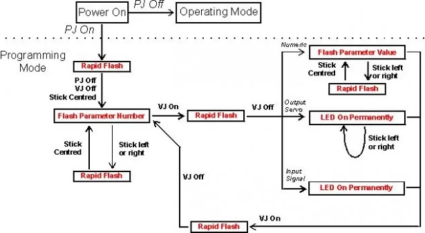
Programming the switch is performed by moving the control that is connected to the switch input, installing and removing the video mode jumper and watching the output LED.
You can exit programming mode at any time by removing the power. You can alter just a single parameter, or any number of parameters in programming mode.
The following diagram shows the various states involved in programming the switch. In this diagram PJ refers to the Programming Mode Jumper and VJ to the Video Mode jumper.
For more detail: Servo Camera Switch using PIC12F675 microcontroller


