
Summary of H-Bridge Microchip PIC Microcontroller PWM Motor Controller
This tutorial explains how to control a DC motor's speed and direction using the Microchip PIC16F690 microcontroller's PWM peripheral in full bridge mode. It details the relationship between pulse width, duty cycle, and motor voltage, providing a complete hardware setup with an H-Bridge circuit and software tools for implementation.
Parts used in the PIC16F690 DC Motor Controller:
- PICJazz 16F690 learning board
- 5 to 6 volt geared DC Motor
- Four 2K2 Ohm ¼ watt resistors
- Four BC639 transistors
- Four 1N4148 diodes
- One 100nF (0.1uF) 16 volt capacitor
- JazzMate 2576-5V power board
- Microchip MPLAB IDE v8.0 or higher
- HITEC PICC-Lite Version 9.60PL1
- Microchip PICKit2 Programmer
One of the advantages using the Microchip PIC microcontroller Pulse Width Modulation or PWM for short is; this PWM peripheral circuit is designed to control the DC motor using the full bridge mode PWM feature. The PWM peripheral works by supplying the correct signal to the H-Bridge DC motor circuit such as speed controlling and changing the DC motor direction. Therefore on this tutorial we will learn to use this sophisticated feature offered by Microchip PIC PWM. For those with the AVR microcontroller background this is also a good chance to learn the beauty of the different between AVR and PIC microcontroller especially in the PWM peripheral features.
From the PWM timing diagram above we could see that by changing the pulse width we could change the average voltage receipt by the DC motor; the wider the pulse width; the higher the average voltage receipt by the DC motor. The shorter the pulse width, the lower the average voltage receipt by the DC motor. Therefore by varying the pulse width we could vary the DC motor speed. The ratio between the pulse width and the total length of the pulse (time on plus time off) is called duty cycle, so by saying 100% duty cycle means the DC motor is in it’s full speed and 10% duty cycle the DC motor is in it’s 10% of speed. We are going to use this following H-Bridge circuit schema on our project: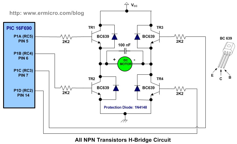
The circuit above basically is the H-Bridge transistor circuit which connected to the PIC 16F690 PWM pins through the PIC PWM output ports P1A, P1B, P1C and P1D. For more detail how the H-Bridge circuit works you could refer to the “Using Transistor as a Switch” posted on this blog.
The following is the list of hardware and software used in this tutorial:
1. PICJazz 16F690 learning board from ermicro (the PICJazz 16F690 schema)
2. One 5 to 6 volt DC Motor (in this project I’am using geared DC Motor)
3. Four 2K2 Ohm ¼ watt resistor for the H-Bridge circuit
4. Four BC639 transistors (or equivalent) for the H-Bridge circuit
5. Four 1N4148 diodes for the H-Bridge circuit
6. One 100nF (0.1uF) 16 volt for the H-Bridge circuit
7. JazzMate 2576-5V power board, the 5 volt switching power supply from ermicro for the H-Bridge circuit.
8. Microchip MPLAB IDE v8.0 or higher
9. HITEC PICC-Lite PICC-Lite Version 9.60PL1
10. Microchip PICKit2 Programmer
In this tutorial first we will learn how to use the basic single output PWM mode and later on we will use the full bridge PWM mode for controlling the H-Bridge motor circuit.
1. The PIC16F690 Microcontroller PWM peripheral
The heart of PIC16F690 PWM lays on the TIMER2 peripheral, this timer is used as the basic counter generator used by the PWM peripheral to generating the PWM pulse, the following is the PIC 16F690 simplify PWM peripheral diagram (for complete explanation please refer to the datasheet):
For more detail: H-Bridge Microchip PIC Microcontroller PWM Motor Controller
- How does changing the pulse width affect the DC motor?
Changing the pulse width varies the average voltage received by the motor; wider pulses increase speed while shorter pulses decrease it. - What is the duty cycle ratio defined as?
The duty cycle is the ratio between the pulse width and the total length of the pulse including time on plus time off. - Does a 100% duty cycle result in full motor speed?
Yes, a 100% duty cycle means the DC motor is at its full speed. - Which timer peripheral generates the PWM pulses in the PIC16F690?
The TIMER2 peripheral acts as the basic counter generator used to produce the PWM pulses. - Can this project be used by users familiar with AVR microcontrollers?
Yes, it serves as a good opportunity to learn the differences between AVR and PIC microcontroller PWM features. - What components form the H-Bridge transistor circuit?
The circuit consists of four BC639 transistors, four 2K2 Ohm resistors, four 1N4148 diodes, and one 100nF capacitor. - Which software tools are required for this tutorial?
The project requires Microchip MPLAB IDE v8.0 or higher and HITEC PICC-Lite Version 9.60PL1. - How is the motor direction changed in this setup?
The PWM peripheral changes the DC motor direction by supplying correct signals to the H-Bridge DC motor circuit.

