Summary of Soldering Station
Summary: This article describes a DIY Weller-style soldering station by Martin Kumm: an Arduino shield driving a Weller soldering tip using a precision op-amp, power MOSFET, user controls, and a display. The author adapted the design to include a 1.8 inch SPI color TFT, replaced buttons with a potentiometer, added a standby mode that lowers tip temperature to 170°C when docked using a pullup-sensed holder, and improved hardware safety for startup and failures.
Parts used in the DIY Weller-style soldering station:
- Arduino (shield form factor)
- Precision operational amplifier (OpAmp)
- Power MOSFET
- Two buttons (original design)
- Potentiometer (used instead of buttons)
- 1.8 inch SPI TFT color display
- Pullup resistor for tip holder sensing
- Metal holder pipe (tip holder)
- Weller soldering tip
At the fpv-community.de Forum I read about a DIY Weller station designed by Martin Kumm. Basically an Arduino shield to drive a Weller soldering tip. As there is not much to it, the board simply contains an precision OpAmp, a power MOSFET, 2 buttons for adjusting the temperature and a display to show the current values. This design looks like a good starting point for my own advanced project. As I have lately discovered a 1,8 inch SPI TFT at banggood.com for an amazing price ( ~ 4.60 $ / 3,70 €), I started using them regularly in my projects. So I surely wanted to use it with this soldering station as well.
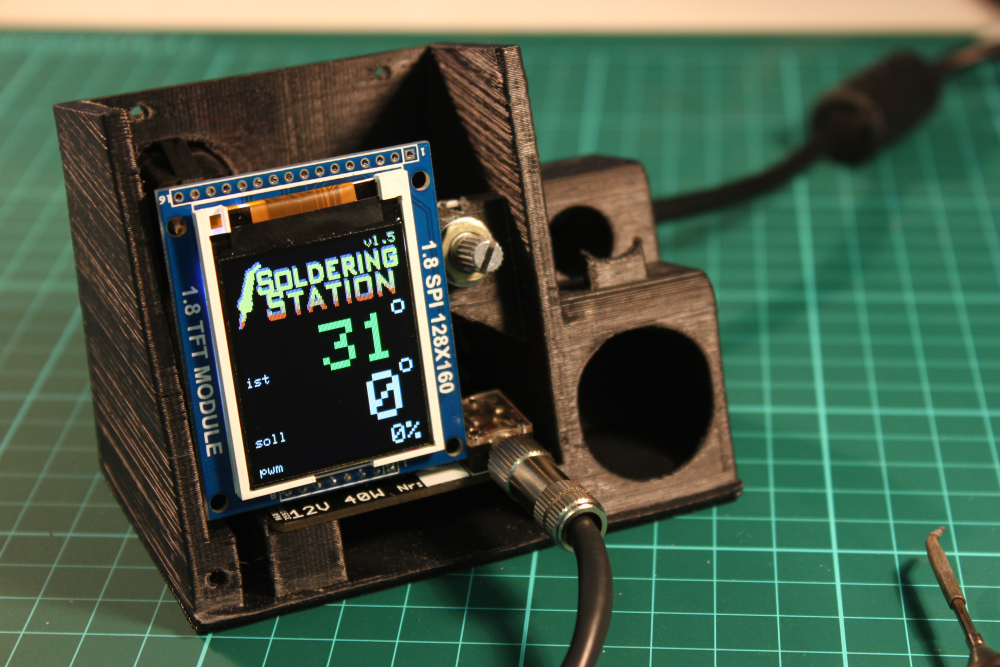
The hardware design was rather hobbyish and needed to be tuned to provide the security not to kill your soldering tip while starting up or in case of a software/hardware fail. The bigger changes I made to the original design were the nice color Display, a poti instead of the buttons (I think it’s easier to adjust) and a standby mode.
The standby mode will decrease the temperature to a 170°C value when the soldering tip is in the holder. This works simply by having a pullup resistor connected to the metal holder pipe which is connected to a digital input. The soldering tip itself is connected to ground potential and will put the digital input to ground level as well when placed in holding position. For reheating the station only takes about 3 seconds which is fast enough in most cases.
For more detail: Soldering Station
- What is the basic electronic design of the soldering station?
The board contains a precision OpAmp, a power MOSFET, user controls, and a display to drive a Weller soldering tip. - Can I use a 1.8 inch SPI TFT with this station?
Yes, the author integrated a 1.8 inch SPI TFT color display into the design. - Why was a potentiometer used instead of buttons?
The author replaced buttons with a potentiometer because it is easier to adjust temperature. - How does the standby mode work?
The standby mode lowers the temperature to 170°C when the tip is placed in the holder, detected via a pullup resistor and digital input. - How is the tip presence detected?
The metal holder pipe is connected via a pullup resistor to a digital input; the soldering tip is grounded and pulls the input low when docked. - How fast does the station reheat from standby?
Reheating the station takes about 3 seconds. - Did the author change hardware for safety?
Yes, the hardware was tuned to provide safety during startup and in case of software or hardware failure.