Summary of 8-CHANNEL RF RELAY CONTROL CIRCUIT RS232 PC PIC16F628
This article describes an 8-channel RF relay control circuit using a PIC16F628 microcontroller and RS232 communication. The system allows wireless control via 433 MHz RF modules and PC software, featuring sound control capabilities for specific buttons. It includes circuit design, PCB layout, and simulation files (ISIS) with PicBasic Pro source code.
Parts used in the 8-Channel RF Relay Control Circuit:
- PIC16F628 microcontroller
- RS232 port interface
- Max232 chip
- RF modules (433 MHz)
- 8 Relays
- Two LEDs for status indication
- PC program (pcrf.exe)
- mscomm32.dll library
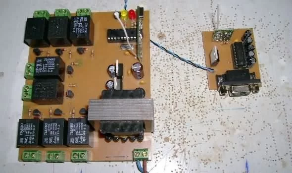
Relay control circuit is built on a computer via the rs232 port com pic16f628 microcontroller RF modules (433 mhz) can be controlled wirelessly with 8 relay with rs232 communication max232 project belongs to isis…Electronics Projects, 8-Channel RF Relay Control Circuit RS232 PC Pic16f628 “microchip projects, microcontroller projects, pic16f628 projects, picbasic pro examples, “
Relay control circuit is built on a computer via the rs232 port com pic16f628 microcontroller RF modules (433 mhz) can be controlled wirelessly with 8 relay with rs232 communication max232 project belongs to isis simulation and ares pcb drawings source picbasic codes. One of the buttons while the other two have the control program with sound control. No information about the volume control button on the project, which has been tested.
Sharing makes the Powerball forums @BiqaLi

Description;
pcrf\pc programlar\pcrf (pc) folder in which to copy the file into c:\windows\system32 called mscomm32. then
We run the program called pcrf, and we select our cards to the appropriate attribute from the seçenğini the screen warning saying yes to com1 of the circuit we wanted to establish a remote connection with the computer
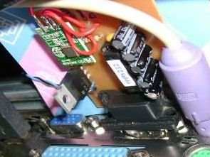
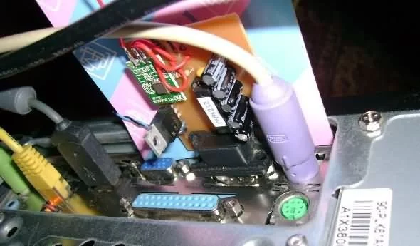
There are two LEDs on the card any energy verdğimizde Yates
When we say yes while the other led and computer connectivity with means provided
then the pc programindan 1/0 konumlarina bringing you can pull the relays.
the circuit completely.
circuit design program @umut WINS resource www.digitalruh.com
circuit pcb design @mert53
circuit trial-review @ biqali
Source: 8-CHANNEL RF RELAY CONTROL CIRCUIT RS232 PC PIC16F628 alternative 8-channel-rf-relay-control-circuit-rs232-pc-pic16f628.rar alternative link3
- How is the relay control circuit connected to the computer?
The circuit connects via the RS232 port using a Max232 chip for communication. - Can the relays be controlled wirelessly?
Yes, the system uses 433 MHz RF modules to control the 8 relays wirelessly. - What microcontroller is used in this project?
The project utilizes the PIC16F628 microcontroller. - Does the system include sound control features?
Yes, one of the buttons provides sound control functionality. - What file must be copied to run the PC software?
The mscomm32 file must be copied into the C:WindowsSystem32 folder. - How many LEDs are present on the circuit board?
There are two LEDs on the card to indicate energy and connectivity status. - What programming language was used for the source code?
The project source code is written in PicBasic Pro. - Which software is used for circuit simulation?
The project belongs to ISIS simulation software for electronics projects.