
Summary of 2 Digit up/down Counter using PIC16F628A
This article describes a two-board microcontroller project featuring a PIC16F628A experimental board and a PIC12F629 2-digit up/down counter. Both circuits support In-Circuit Programming via PICkit-2. The design allows for modifications like adding alarms, buzzers, or expanding the display to three digits, though multiplexing reduces brightness with extra digits. Testing involves checking segment illumination by applying 5V to specific pins without the chip installed.
Parts used in the 2 Digit Up/Down Counter:
- PIC16F628A Microcontroller
- PIC12F629 Microcontroller
- PICkit-2 Programmer
- Experimental PC Board
- Surface-mount components
- Diode
- 100n Surface Mount Capacitor
- Two Surface-Mount Transistors
- Up/Down Buttons
- 22k Resistors
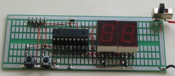
This project comes via two circuits on 2 boards. The first circuit is designed around a PIC16F628A. It has been presented on an experimental PC board using surface-mount components and was built in less than 1 hour, with about 2 hours to write and finalise the program. See P1, P2
The second circuit uses a PIC12F629 to produce a 2-Digit Up/Down Counter (see P3).
Both use “In Circuit Programming” via PICkit-2.
P5 Describes the up/down counter displaying the “gear” for motorcycles and racing cars.
The project shows what can be done with a micro and you can modify it to set an alarm at any count-value or set a limit such as “count-to-60.” You can add a buzzer or relay or increase the display to 3 digits. You need to remember that each additional display will reduce the illumination of each digit as they are “multiplexed (time-sharing).”
The experimenter PC Board shows the five “In Circuit Programming” pins and a diode on the positive rail to drop the 6v supply to 5.4v. The board also has a 100n surface mount capacitor and two surface-mount transistors. The Up/Down buttons have 22k resistors. TESTING THE CIRCUIT
Check the circuit by removing the chip and taking pins 6 and 18 to the 5v rail ad make sure segment “A” illuminates. Do the same for all the other segments.
The circuit diagram does not have any voltages marked on it as the circuit is DIGITAL.
All the “lines” or “wires” or pins of a microcontroller will have rail voltage (5v) on them when they are HIGH and when you come to a resistor, the resistor will drop a certain voltage. The voltage it will drop will be the difference between rail voltage and the voltage developed across the component it is driving. If it is driving a LED, the LED will drop a characteristic voltage of between 1.7v and 3.6v, depending on the colour.
If the component is a transistor, the voltage developed between the base and emitter will be about 0.7v.
For more detail: 2 Digit up/down Counter using PIC16F628A
- How long did it take to build the first circuit?
The experimental PC board was built in less than 1 hour. - Can you modify the project to set an alarm?
Yes, you can modify it to set an alarm at any count-value. - What happens if you increase the display to 3 digits?
Each additional display will reduce the illumination of each digit because they are multiplexed. - Does the circuit diagram have voltages marked on it?
No, the circuit diagram does not have any voltages marked on it as the circuit is digital. - How do you test the circuit segments?
Remove the chip and take pins 6 and 18 to the 5v rail to make sure segment A illuminates. - What voltage drops across a driving LED?
An LED will drop a characteristic voltage of between 1.7v and 3.6v depending on the color. - What voltage develops between the base and emitter of a transistor?
The voltage developed between the base and emitter will be about 0.7v. - How many programming pins are shown on the experimenter PC Board?
The board shows five In Circuit Programming pins.
