Most of the ideas in this chapter can be found on the pages of this website, but just in case you want to go over the capabilities of the ‘508A, we have brought them together.
Quite often when you are programming, the first thing you will run out of is output lines. Many projects need lots of drive lines and if you need more than about 8, you should go to another micro-controller.
Don’t expect an 8-pin chip to perform the impossible.
The designers of the ‘508A have done an amazing job providing 5 output lines (and one input line) in an 8-pin chip, but even so, many projects run out of drive-lines.
On other pages of this course we have shown how to expand the drive lines with a binary counter or shift register. This can increase the lines to more than 10 however if you want to add just one or two more devices than the chip is directly capable of handling (5), there are clever ways to connect them to the chip.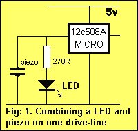
1. LED AND PIEZO ON ONE LINE
One of the simplest combinations is a LED and Piezo on a single drive-line as shown in fig: 1. These can be combined because the requirements of a LED are different to a piezo. A LED requires a constant HIGH for it to illuminate while a piezo requires a HIGH-LOW-HIGH waveform at approx 3kHz to produce a tone.
If the mark-space ratio of this waveform is kept short as shown in fig: 2, the LED will only illuminate very dimly. A short mark-space ratio means the “mark” is very small compared to the “space”. A very short on-time (mark) and a long off-time (space) will not affect the tone from the piezo but will deliver very little energy to the LED and this is exactly what we want.
On the other hand, each time the LED is activated, only a very small click will be heard, and this will hardly be noticeable. In this way the two devices can be combined on the same line.
2. LED AND PUSH BUTTON ON ONE LINE
In this book, we show how to connect two and up to five or more push buttons on a single input line and generally you will not have any problems adding buttons to a project. But if you want to add a secret reset button (or a “cheat” button, for example), it can be added across an existing LED as shown in fig: 3.
The resistor between the switch and micro acts as a safety resistor to prevent the output of the chip being damaged if the switch is pressed when the LED is activated, and it also acts as a dropper resistor for the LED.
These two items will work in combination because the impedance of the LED is very high when no voltage is across it and when the micro turns the line into an input line, it sees the LED as a high impedance. In other words it is not detected so that when the switch is pressed the micro only sees the switch as a LOW.
3. DIFFERENT PROGRAMS IN THE CHIP
Up to 5 different programs can be burnt into a single ‘508A and the required program can be accessed by soldering a resistor between one of the outputs and the “input-only” line – GP3, as shown in fig: 4.
During turn-on, a special program will put a HIGH on each output in turn and the output containing the resistor will determine the program.
Combining 5 programs in one chip will reduce inventory costs as the required program can be selected by fitting the resistor in the appropriate place on the board.
4. LINE REVERSAL
If a device is connected between two output lines as shown in fig: 5, a program can be written so that the device sees a voltage reversal. When one output is HIGH the other is LOW and this is then reversed.
The drive lines have a maximum output current of 25mA and this is enough to drive a number of different devices. If a red LED is connected in one direction and a green LED in the opposite direction, they can be turned on and off individually, as shown in fig: 6.
If the two LEDs are placed near each other or combined in the one LED (called a tri-coloured LED), they will produce a number of colours including orange, depending on the mark-space waveform delivered to each LED.
A single LED containing red and green chips is available in 2 or 3 lead versions. The wiring for a 3-leaded tri-colour LED is shown in fig: 7. The tri-leaded version is shown in fig: 6.
Tri-coloured LEDs are fairly expensive but if the project can cover the expense, they can be the basis of “running message” displays and simple TV screens.
If you connect a piezo to two out-of-phase lines as shown in fig: 8b, the sound produced will be slightly louder than the arrangement in fig: 8a.
When we talk about a piezo we really mean a PIEZO DIAPHRAGM. A piezo diaphragm is a passive device and is very similar to a capacitor as far as the circuit is concerned. Ceramic substrate on a metal diaphragm causes the metal to “dish” and bend to produce a high pitched sound. The size of the voltage (the amplitude) determines the intensity of the sound and the frequency of the waveform determines the tone.
The voltage across the piezo from one drive line is about 5v whereas the voltage seen by the piezo from two reversing lines is about 10v. Unfortunately this doesn’t produce twice the sound output but the sound is slightly louder. If you want a louder output you should use a better-quality high-output diaphragm (such as from a Christmas card).
The loudest output is a piezo siren and this is an active device containing a transistor oscillator and choke. These units operate from 5v to 15v and produce a very loud output while consuming only about 10mA to 15mA.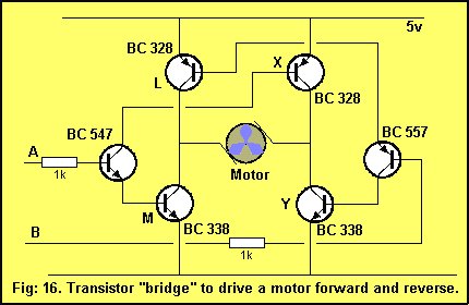
5. DRIVING LEDs
Each output line of a ‘508A can only deliver about 25mA. This current is determined by the size of the transistor delivering the current. The transistor inside the chip is only very tiny and if a higher current is drawn, it may be damaged.
When a resistance of 200 ohms is connected from output to ground, a current of 25mA flows (when the output is HIGH). If the resistance is reduced, a higher current flows. This means a resistance of 200 ohms or higher is required to make sure the current flow is less than 25mA.
But if a LED is placed on the output, how is the resistance worked out?
A LED drops a voltage across it according to its colour. This is called the CHARACTERISTIC voltage or the CHARACTERISTIC VOLTAGE DROP. This voltage is constant, no matter how bright the LED is illuminated.
For a red LED the characteristic voltage is 1.7v.
For an orange LED the characteristic voltage is 1.9v.
For a green LED the characteristic voltage is 2.1v.
LEDs cannot be connected directly to the output of a drive-line without a voltage-dropping resistor.
The reason is very technical but basically a red LED does not turn on AT ALL until exactly 1.7v is placed across it and if the voltage tries to rise above 1.7v, the LED will glow brighter, allow a very high current to flow and will be damaged.
The only way to prevent damaging the LED is to provide it with a very accurate supply voltage or simply connect a resistor in series. If the value of the resistance is worked out, an accurate current can be delivered to the LED and everything will be ok. The LED will last 100 years!
For more detail: 10 tricks for interfacing to the PIC16C508