Summary of PIC Light Chaser
This article details a PIC16F84-based 8-light chaser circuit, demonstrating how to program a microcontroller for sequential LED lighting. Unlike fixed hardware circuits, this design allows flexible light sequences through software reprogramming alone. The project requires an existing August-programming circuit and utilizes assembly code to rotate bits on Port B with specific timing delays.
Parts used in the PIC Light Chaser:
- PIC16F84 microcontroller
- IC socket
- LEDs (8 units)
- August programming circuit
- 75kHz oscillator
- Assembly language code (DEMO.ASM)
This month I am continuing with the PIC projects that I started in August. To be able to build this circuit you must build the August circuit which allows you the ability to program PIC’s.
The circuit this month is a simple 8 light chaser built around a PIC. This will demonstrate how easy it is to program a PIC and to utilize it in a circuit. The circuit works as follows. When power is supplied to the circuit the PIC resets and starts to process instructions that are programmed into it.
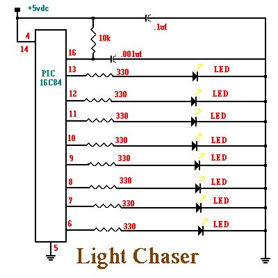
The program will turn on each LED in sequence with a small delay between each one. It will continue to do this until power is removed. The nice feature with this circuit is that you can program it to perform many complex lighting sequences. Normally you would have to rebuild a hardware based circuit to change the light sequence. With a PIC all you need to do is reprogram it and plug it back into the circuit. I am assuming that you will be using an IC socket. The circuit is show below and then I will discuss the program that is programmed into the PIC.
;File DEMO.ASM
;Assembly code for PIC16F84 micro controller
;Blinks LED’s on the outputs in a rotating pattern.
;With 75khz osc, each LED stays on half a second.
;CPU configuration
; (its a 16F84,RC Oscillator, watchdog timer off, power-up timer on)
processor 16f84
include <p16f84.inc>
_config _RC_OSC &_WDT_OFF &_PWRITE_ON
;Declare variables at 2 memory locations.
J equ H’1F’ ;J=Address hex 1F
K equ H’1E’ ;K=Address hex 1E
;Program
org 0 ;start at address 0
;Set port B as output and initialize it
movlw B’00000000′ ;w : =00000000 binary
tris PORTB ;port B ctrl register := w
movlw B’00000001′ ;w := 00000001 binary
movwf PORTB ;port B itself := w
;Rotate the bits of port B leftward
mloop: rlf PORTB,f
;Waste some time by executing nested loops.
movlw D’50’ ;w := 50 decimal
movwf J ;J :=w
jloop: movwf K ;K :=w
kloop: decfsz J,f ;J = J -1, skip next if zero
goto kloop
decsz J,f ;J = J – 1, skip next if zero
goto jloop
;Do it all again
goto mloop
end
The program works as follows. The first few lines in the program are what is called comment lines. Comment lines assist us in documenting what each part of the programs function is. If a program is commented well, then it will be easier later own to understand why the program was written the way it was. Any line that begins with a semicolon is a comment line and will be ignored when the assembler is run. The assembler is another program that will convert these written instructions and convert them to binary data to be programmed into the PIC.
For more detail: PIC Light Chaser
- What is required before building this circuit?
You must first build the August circuit which enables you to program PICs. - How does the circuit operate when power is supplied?
The PIC resets and begins processing instructions programmed into it immediately. - Can I change the lighting sequence without rebuilding hardware?
Yes, you only need to reprogram the PIC and plug it back into the circuit. - Which microcontroller is used in this project?
The project uses a PIC16F84 microcontroller. - What happens if I remove power from the circuit?
The sequence stops running once power is removed. - What is the purpose of comment lines starting with a semicolon?
They document the function of each part to make the program easier to understand later. - What component converts the written instructions to binary data?
The assembler program converts the written instructions to binary data for the PIC. - Why is an IC socket assumed for this project?
An IC socket is recommended to allow easy removal and replacement of the PIC for reprogramming.