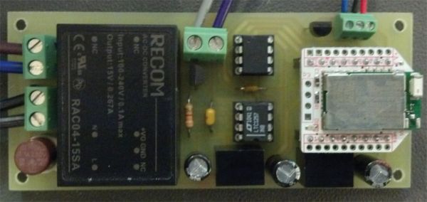
Despite the initial investment, solid state lighting (SSL) has proven to be a viable alternative over conventional technologies due to the combined savings in energy consumption and maintenance costs, as well as design flexibility. Furthermore, increased energy savings can be realized with active intelligence such as occupancy and ambient light sensors, as well as external dimming controls to eliminate excessive lighting. Since there are a wide variety of constant current LED drivers requiring a 0-10 volt DC input for dimming control available, the focus of this discussion will be utilizing these drivers with a wireless interface.
The overall concept is relatively straightforward. A data stream containing the desired control voltage is transmitted and then received by a module that has been configured to act as a transparent RS-232 interface to a microcontroller. The microcontroller in turn interprets the data stream and loads the appropriate values into the data registers of a digital-to-analog converter to produce the desired control voltage.
Due to the widespread use of devices such as laptops, tablets, and cell phones, the Bluetooth connection protocol was selected for the transmission of the control voltage data stream. On the reception side, the876-1005-ND evaluation board for the Panasonic PAN1555 was selected for its versatility and ease of use in prototyping.
The selection of the microcontroller was based upon 3.3 volt operation and the requirements of having a USART, a programmable internal oscillator, and sufficient yet not excessive I/O. Due to the consideration of future implementations requiring PWM for control and the storage of non-volatile data, the features of PWM and EEPROM were added to the requirements. The PIC12F1822-I/P-ND was ultimately decided upon.
The DAC selection was based upon the requirements of a single supply, an output voltage of at least 10 volts, a serial interface, 12-bit resolution, and an external reference input. The LTC1257IN8#PBF-ND proved to be a worthwhile candidate.
In order for the DAC to produce the necessary output range, a 10 volt voltage reference is required. TheLM4040CIZ-10.0/NOPB-ND was selected due to its ±0.5% tolerance, TO-92 package, and 15mA output current capability.
Several criteria were considered in selecting the power supply for the circuit. First, the supply voltage needs to be sufficient enough to allow the DAC to provide a 10 volt output. According to the specifications of the LTC1257, VCC needs to exceed the reference voltage (10V) by 2.7 volts, making the selection of a 15 volt supply appropriate. The desire for an enclosed board-mount supply with a minimal footprint and at least 200 mA of output current resulted in the selection of the 945-1068-ND power module.
While the DAC is powered directly from the 15 volt supply, the Bluetooth module requires a 3.3 volt supply, which will also power the microcontroller. As dropping down from 15 volts to 3.3 volts with a linear regulator would be inefficient, the 945-1661-5-ND was selected due to the fact that it’s a switching regulator having a small footprint, a maximum input voltage of 28 volts, and a 500 mA output capability.
To facilitate powering external devices such as active cooling, the 945-1648-5-ND was chosen to produce a 5 volt supply, again due to it being a switching regulator with a maximum input voltage of 28 volts and a 500 mA output capability. In conjunction with this 5 volt supply, the 296-6549-5-ND “Rail Splitter” was selected to produce a voltage equal to one-half of the DAC output to correspond with, and allow for linear control of the 5 volt powered devices. Terminal block part number 277-1274-ND was utilized for connection to the 5 volt supply and “Rail Splitter” voltages.
To accommodate connection to the AC power source and the constant current LED driver wires, terminal block part number 277-1247-ND was selected due to its 0.200” spacing, the accommodation of 14-30 AWG wire, and the capability of handling up to 10 amps of current.
As previously stated, the PAN1555 Bluetooth evaluation board needs to be configured to act as a transparent RS-232 interface to the microcontroller, and the microcontroller needs to be programmed to receive the control voltage data stream and load the DAC registers accordingly. Likewise, a means of transmitting the control voltage to the Bluetooth module needs to be addressed.
The factory default settings on the Panasonic PAN1555 Bluetooth module on the evaluation board need to be reconfigured for use in this particular application. This is accomplished using AT commands sent via a wired RS-232 interface. The use of a “Smart” USB cable such as the TTL-232R-3V3-WE simplifies this task. There are two important considerations to take note of when using this cable. First, in order to make the FT232R in the cable appear as a virtual COM port, it is necessary to download the free USB drivers from FTDI at http://www.ftdichip.com. Secondly, despite the fact that the TTL levels on this cable are at 3.3 volts, the cable VCC supply voltage is at the USB port voltage of 5 volts. In order to power the evaluation board during configuration, this supply voltage must be regulated down to 3.3 volts. Regulation requires nothing more than a couple of components such as the combination of the L4931CZ33-AP 3.3 volt regulator and the EEA-GA1H2R2
For more detail: Wireless Control of Linearly Dimmed LED Drivers

