When I saw the Aurora LED 9×18 Instructable, I was inspired. However, it’s built on the PIC microcontroller while I am most familiar with the AVR microcontrollers. Plus, I already have the development and programming environments for AVRs, so I set about a redesign as a personal challenge. I wanted to make something (almost) just as nice, that did not require as many components, was less expensive, and could be soldered by hand (albeit maybe taking a lot of time). The result is this Instructable, the ChromoDisk.
The ChromoDisk is very similar to the Aurora LED. It has the same 9 rings of 18 LEDs and every ring has to be the same color and brightness due to the multiplexing approach. This device uses pulse-width modulation (PWM) instead of resistors to limit the power fed to the LEDs, so while it takes less assembly time and components, you need to be a little careful about how you write the software. This is a good illustration of the tradeoff you need to make when you design with microcontrollers. You need to strike a balance between what you do in hardware and what you do in software. I am NOT saying that LED Artist’s approach with all the resistors is bad, it’s just a design choice and this is one alternative. More about this later.
Let’s start with the design parameters:
-
- Easily available, low cost components
-
- Low component count
-
- Fits within a low-cost tier for PCB manufacture
-
- Hand-solderable
-
- Multiple power supply options
- Easily programmable
The design you see here has been through 4 generations. You can make a lot of mistakes in PCB design and layout, and I did. Little things like forgetting to mirror components (battery pack) to the back of the board, not accounting for total current loads on chips (overheated micro), and switching transients (turning all the LEDs on at once) wreck a design. I ran into all of these and more. I think this final version gets it about right though.
The components I’ve chosen barely fit into the tight space. I picked the largest SMT components that I could to facilitate manual handling and ease of soldering. In the end, because of the limited real estate, I was not able to allow both battery pack and DC power jack, so you need to choose which one you’ll use. Also, everything fits within a 100 mm square, a 4 inch disk, which is one of the pricing tiers typical of most PCB manufacturers. Anything bigger bumps you to the next pricing tier. Since area and cost goes up as the square of the radius, it’s a good idea to limit the size. Routing out the circular shape is normally included in the board price.
The AVR micros are fairly easy to program. The code I’ve provided is entirely interrupt-driven and written in assembly language. It might be a bit less readable than C or some other language, but it’s about as efficient as you can get. I don’t claim to be the best programmer, but it seems to work pretty well and I was able to derive some new modes using code from other modes. It’s designed to be hacked!
Here is the list of parts for the ChromoDisk, with Mouser P/N, description, and quantity:
| 667-ERJ-3EKF1201V | Thick Film Resistors-0603 1.2K ohms 1% | 13 |
| 667-ERJ-3EKF6800V | Thick Film Resistor-0603 680 ohms 1% | 3 |
| 667-ERJ-3EKF1002V | Thick Film Resistor-0603 10K ohms 1% Tol | 1 |
| 81-GRM188R71H104KA93 | Capacitor (MLCC)-0603 0.1uF 50volts X7R 10% | 1 |
| 512-FDN338P | MOSFET Small Signal SSOT-3 P-CH -20V | 3 |
| 771-PMST2369115 | Bipolar Small Signal NPN 15v 200mA 500MHz | 12 |
| 556-ATTINY4313-SU | Microcontroller AVR 4KB FL 256B SRAM 1.8-5.5V | 1 |
| 612-TL3315NF250Q | Tactile Switch LOPRO 250GF SMD | 1 |
| 611-KSC741GLFS | Tactile Switch 4.3mm IP67 3N Soft Actuator | 1 |
| 798-DF1BZ-6DP-2.5DSA | 2.5MM V DBL ROW HDR | 1 |
| Common cathode RGB LEDS | 162 | |
| Custom PC Board | 1 | |
| 598-AVE227M16X16T-F | Al Electrolytic Cap – 220uF 16V 85C Case 6.3 x 7.7 | 1 |
| 163-5030-E | DC PWR JACK 2.0MM X 5.5MM SMT | 0/1 |
| 12BH331P-GR | Battery Holder 3 AA PC LEADS | 1/0 |
| In-System Programmer for AVR microcontrollers | 1 |
A couple of comments here. First, you’ll notice that you have to choose either the DC power jack or the solder-on battery pack (you can use one with wire leads if you like, but I designed it to use the version with pins). There’s a mounting hole in the center for whatever you want, but the battery pack will obscure it. I used it to secure battery packs before I added the PC mount pack. Second, I don’t have a spec for the RGB LEDs. It’s entirely up to you which ones you choose. Since I eliminated the current-limiting resistors on the LEDs by using PWM in software, you can adjust the brightness of the LEDs over a wide range by adjusting a couple of simple parameters at the top of the code. This allows you to accommodate LEDs with various current specs as long as they can take the surge current of the PWM approach.
The pinout for the LEDs is red / cathode / green / blue. I have tried assembling boards with diffused and water-clear LEDs. Diffused give more uniform color and brightness; clear give brighter light that floods farther and they have interesting effects with angle of view, but non-uniformity in LEDs can result in color hot-spots. The PWM approach has some limitations there.
I’ve ordered the parts in large enough quantities that I can provide the kit of parts and the custom board (but not the ISP programmer). Let me know if you’re interested. Given the time involved, I’m not going to make any money on it. That wasn’t really the point. It was intended to be a challenge and something fun for people to exp
eriment with.
Step 1: The Build – Layer 1
There are five phases to the build:
– Solder on the small passive SMT components and transistors
– Solder on the larger SMT components
– Program the microcontroller
– Solder on the LEDs
– Solder on the power source
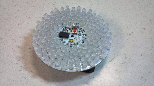
The idea here is to put on components that don’t interfere with each other in layers. The board is very crowded, so it’s essential to do this to make the build as easy as possible. Here’s a picture of the board you’re starting with. Let’s go!
Layer 1 – SMD Components … Most of them
The passive components go on first because they are the smallest and easiest to lose if you tilt the board. You need as much clear area as possible when you’re soldering these. You can use the “skillet” / oven method, or hand solder them. I did it all by hand. SparkFun has a good tutorial on hand-soldering SMT components, so I won’t try to duplicate that here. Solder on all of the resistors and the bipolar transistors first. The MOSFETs are static-sensitive, so adding in the other components first will help protect them. Don’t put on the microcontroller, the large electrolytic cap, the 6-pin connector, the LEDs, the power connector / battery pack, or the capacitor on the back yet. Solder on
the MOSFETs last in this layer.
Step 2: Layer 2 â Large SMD Components
Now that you’ve got the small components in place, add in the two switches. Put the large one on the pads labeled Mode, since it’s the one you might use the most. The shape of the switch makes it a little harder to solder in place. I found the key to be soldering one contact in place, with the switch centered on the pads. If you heat up the other pads, and use good flux, the solder will wick in underneath pretty readily. The other switch goes on the Reset pads. It has more exposed contacts, so it’s easier to solder down. Add in the large 220 uFd cap, the microcontroller, the small cap on the back opposite the microcontroller, and the 6-pin connector. Note: the image here shows the LEDs installed. If you’re following along while building one of these, they aren’t there yet!
Step 3: Layer 3 â Programming
At this point, you have everything on the board to program the microcontroller except the power connector. You’ll need to jumper your power source to the two holes for the battery pack. Make sure you respect the polarity! Depending upon the ISP you’re using, you’ll need to connect the power before or after you connect the programmer to the 6-pin connector. Check the instructions for your programmer. An initial program is provided here, in both source and code formats. The microcontroller does not come pre-programmed, so you’ll need to do that now. The advantage of doing it here, rather than at the end, is that you can test as you go. One of the modes in the code lights up each color in each ring. This allows you to verify that your LEDs and other components are soldered in place correctlyas you progress through the build. To do this, you can connect the power when needed. I did this with the battery pack by inserting it in the holes without soldering it in place. If you chose the DC power jack instead, it will be a bit more difficult. You could solder that on, but it will make manipulating the board a little more difficult during the rest of the build process. Here’s what it looks like with the battery pack in place.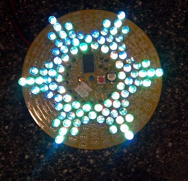
Step 4: Layer 4 – The LEDs
You would have thought that the surface-mount devices would be the hardest part of the build. For me it was the LEDs. The pins are close enough together that it’s easy to get solder bridges. Plus there’s the sheer tedium of soldering 162 LEDs with 4 pins each. One method that works for me is to insert all of the LEDs and verify that they are oriented properly. You can get an inkling if you connect up the power and go to the test mode. Not all of the pins will make contact without soldering, but if you press an LED to one side or the other, it will make contact on all of the pins and you can get it to light up as a quick test. If any of the LEDs are inserted the wrong way, strange things can happen with all the others, because they are all connected into a big matrix. Solder bridges do the same thing, so be prepared with a magnifying glass. And use a quality solder and plenty of flux!
Here’s my approach to the order of soldering. Once you’ve got all of the LEDs in place, solder one pin on each LED in the outer-most ring in place on the bottom side of the board. Make sure that as you solder, the LED is fully inserted so they are all flush with the top side of the board. You can also use the shoulders on the leads to space the LEDs up off the board, but this is a little more difficult to get consistent height. The choice is yours. Thicker overall board with the LEDs up off the board, or slightly thinner and more compact with them all flush.
Next, go around that outer-most ring and clip the leads, leaving a little nub for soldering the other leads later. Then proceed to each of the rings, soldering one lead on each LED and clipping leads. Once you’ve got all of the LEDs tacked in place, go around and solder all of the remaining leads. This goes a lot faster. Make sure you don’t miss any, or you’ll be trying to figure out why some of your LEDs are acting funny.
At this point, you need to test all of the LEDs and make sure they are working, because if you’re using the battery pack it will cover up some of the leads! The DC power jack is not as problematic, since it does not obscure the pins. It’s sometimes very difficult to find bridges, and I don’t have any wise words or troubleshooting steps for you. However, I have found that the board is thin enough that you can shine a light through from the top and inspect the bottom side to find some bridges. If you don’t see a complete ring of light around each LED on the bottom side, there’s likely a bridge there
For more detail: The ChromoDisk
About The Author
Ibrar Ayyub
I am an experienced technical writer holding a Master's degree in computer science from BZU Multan, Pakistan University. With a background spanning various industries, particularly in home automation and engineering, I have honed my skills in crafting clear and concise content. Proficient in leveraging infographics and diagrams, I strive to simplify complex concepts for readers. My strength lies in thorough research and presenting information in a structured and logical format.
Follow Us:LinkedinTwitter