Summary of Simple JDM PIC Programmer
This project describes a DIY JDM serial PIC programmer powered directly from an RS232 PC port, excluding laptop compatibility due to voltage limitations. It utilizes "Win PIC Programmer" software and supports chips like the PIC16f84A and PIC16f828A. The creator designed the PCB using WinQcad with toner transfer etching methods, providing files for standard and mass copper pour layouts to optimize the manufacturing process.
Parts used in the Simple JDM PIC Programmer:
- RS232 Serial Port (PC)
- JDM Programmer Circuit
- Win PIC Programmer Software
- PIC16f84A IC
- PIC16f828A IC
- WinQcad Software
- Toner Transfer Materials
- Toothbrush
I have built this project to burn my small PIC’s
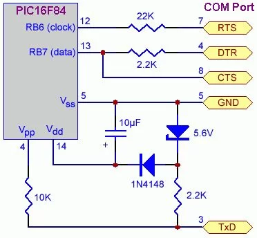
This is a serial programmer works on the RS232 ( PC serial port ), known as JDM Programmer, thanks to the site http://pic16f84.hit.bg/ which contains the schematic and the programmer software.
The programmer is powered from the Serial port itself, so there’s no need to any external power supply.
But be careful this circuit will not work with the Laptop Serial port due to the weak voltages it has.
– I have used a very nice programmer software called “Win PIC Programmer” you can download it from
http://freenet-homepage.de/dl4yhf/winpicpr.html, it’s very stable and powerful.
The project has been tested with the following IC’s :
PIC16f84A
PIC16f628A
Step 1: The schematic
Step 2: The PCB
– I have made the PCB using WinQcad Software it’s easy and has a nice autorouting feature. Please download the PDF document which contains the true scale dimensions.
You will see two files :
PCB.pdf and PCB_copper_pour.pdf
the second one has a “mass copper pour” to save your etching solution and to speed up the etching process without affecting your tracks.
– I used the Toner Transfer method draw the tracks, i can say the output is nice. I have included the steps required to make PCB in the following steps.
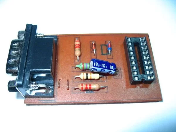
Step 3: Toner Still on the PCB
This output from the Ironing process, you can see the black toner tracks, the paper has been removed using a tooth brush.
For more detail: Simple JDM PIC Programmer
- How is the programmer powered?
The programmer is powered from the Serial port itself without needing any external power supply. - Can this circuit work with a Laptop Serial port?
No, the circuit will not work with the Laptop Serial port due to weak voltages. - What software is recommended for this project?
The article recommends using the stable and powerful software called Win PIC Programmer. - Which PIC chips has the project been tested with?
The project has been tested with the PIC16f84A and PIC16f828A. - What software was used to design the PCB?
The PCB was made using WinQcad Software which features easy autorouting. - What method was used to draw the tracks on the PCB?
The Toner Transfer method was used to draw the tracks. - Why is there a mass copper pour file included?
The mass copper pour saves etching solution and speeds up the etching process. - How can you remove the paper after ironing?
The paper can be removed using a toothbrush after the ironing process.