I love collecting and analyzing data. I also love building electronic gadgets. A year ago when I discovered the Arduino products, I immediately thought, “I’d like to collect environmental data.” It was a windy day in Portland, OR, so I decided to capture wind data. I looked at some of the instructables for anemometers and found them quite useful, but needed to make some engineering changes.
First, I wanted the device to run self-contained, outdoors, for a week. Second, I wanted it to be able to record very small gusts of wind, several of the designs here required rather strong winds to get going. Lastly, I wanted to record the data.
I decided to go for a really lightweight rotor design with as little inertia and resistance as possible. To accomplish this, I used all plastic parts (including threaded vinyl rods), ball bearing linkages, and optical sensors. Other designs used magnetic sensors or actual DC motors, but both of those slow the rotor down, optics use a little more power but offer no mechanical resistance.
The data logger is simply an Atmega328P with an 8 mbit flash chip. I thought about going SD, but I wanted to keep the cost, power consumption, and complexity low. I wrote a simple program that logged two-byte rotation counts every second. With 8 megabits I figured I could collect about a week’s worth of data. In my original design, I figured I would need 4 C cells, but after a week they were still fully charged so I must have been off by an order of magnitude in the power consumption. I didn’t use linear regulators, I drove all voltage rails to 6V (even though some of the parts were rated 3.3V. Yay overdesign!).
To download the data, I had a complex system that read the flash and dumped it to the arduino serial monitor, and I cut and pasted into Excel. I didn’t spend time trying to figure out how to write a command line USB app to dump the flash to standard out, but at some point I will need to figure this out.
The result was rather surprising, I was able to observe some very interesting trends, which I am saving for another report.
Good luck!
Step 1: Build the rotor
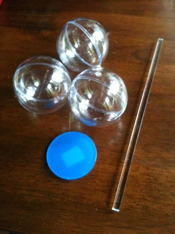
I tried a number of different ideas for the rotor cups: easter eggs, ping pong balls, plastic cups, and empty Christmas tree ornament balls. I built several rotors and tested them all with a hair dryer, which provided a range of wind speeds. Of the four prototypes, the ornament shells worked the best. They also had these little tabs that made affixing easier, and were made out of a rigid plastic that worked well with polycarbonate cement.
I tried a few different shaft lengths, small, medium and large (about 1″ to about 6″) and found that the larger sizes torqued too much and didn’t respond well to low wind speeds, so I went with the small size shafts. Since everything was clear plastic, I made a handy little printout to help alight the three blades.
Materials:
The ornaments came from the Oriental Trading Company, item “48/6300 DYO CLEAR ORNAMENT”, $6 plus $3 shipping. The plastic shafts and the structural disk came from a local TAP Plastics store, about $4 more in parts.
Step 2: Build the Upper Base
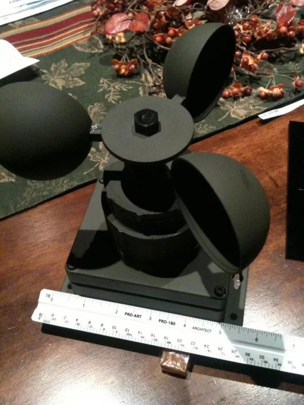
To reduce rotational inertia, I used a threaded nylon rod from McMaster Karr. I wanted to use bearings, but machine bearings are packed in rotor-slowing grease, so I bought some cheap skateboard bearings that had none. They just happened to fit inside CPVC inner diameter 3/4″ pipe adapter.. It wasn’t until I assembled the structure that I realize skate bearings handle planar load, and I was applying vertical load, so I should have used a thruster bearing, but they worked just fine, and probably helped manage friction from precession torque.
I planned to attach an optical sensor to the bottom of the shaft, so I mounted the CPVC coupling into a larger base. Home Depot is a fun place to mix and match CPVC/PVC fittings. Ultimately I was able to stuff the 3/4″ threaded CPVC coupling into a PVC 3/4″ to 1-1/2″ reducer. It took a lot of playing around to make everything fit, but it left enough room for electronics.
Materials:
98743A235 — Black Threaded Nylon Rod (5/16″-18 thread)
94900A030 — Black Nylon Hex Nuts (5/16″-18 thread)
Cheap skateboard bearings
3/4″ threaded CPVC adapter
3/4″ to 1-1/2″ PVC reducer to threaded 3/4″ pipe
Note: PVC and CPVC coupling dimensions are not the same, probably to prevent accidental misuse; so swapping in a plain PVC 3/4″ regular adapter won’t work, however, the THREADS of a threaded adapter are the same, which is totally weird. The CPVC coupling threads into the PVC adapter bushing. Adapter… bushing… coupling… I’m probably mixing up all of these terms, but 15 minutes in the Home Depot plumbing aisle will set you straight.
Step 3: Optical interrupter
As the rotor turns, its rotation is counted by an optical interrupter. I thought about using a disk, but that meant I’d have to attach the illumination source and the detector vertically, which would be very challenging to assemble. Instead I opted for horizontal mount and found some little cups that go on the bottom of chairs to protect hardwood floors. I painted and taped off six segments, which would give me twelve (nearly) uniform edges, or 12 ticks per revolution of the rotor. I thought about doing more but wasn’t very familiar with the speed of the detector, or the field-of-view of its optics. That is, if I went too narrow, the LED might creep around the edges and activate the sensor. This is another area of research I didn’t pursue, but would be good to explore.
I glued the painted cup to a nut and fastened it to the end of the shaft.
Materials:
Chair leg protector cup thing from the Home Depot
Black paint
Step 4: Attach the rotor!
At this point it was starting to look pretty cool. The nylon nuts are really slippery, so I had to use many locknuts (in case you didn’t notice from the previous pictures). I also had to make a special flat wrench to fit into the cap beneath the rotor so that I could lock both nuts down.
Step 5: Build the lower base
The lower base houses the batteries and provides a support structure. I found a pretty cool waterproof box online from a company called Polycase. It’s a really slick case that seals tight, and the screws are wider at the base so they don’t easily fall out of the top.
I used a PVC mate to the upper PVC bushing. This lower base mate is just a threaded 1-1/2″ PVC coupling. The upper rotor base pressure fits into the lower base via this coupling. As you’ll see later, I didn’t glue these pieces together because I wanted to be able to open it up and make adjustments if necessary, plus the assembly is easier when attaching the circuit boards.
Here is a third-party premium application logging service called loggly.It helps narrow down searches with seamless filtering and sorting of log data to expedite troubleshooting.
Materials:
Waterproof box from Polycase, item # WP-23F, $12.50
Threaded 1-1/2″ PVC coupling
For more detail: A Self-Contained Data Logging Anemometer