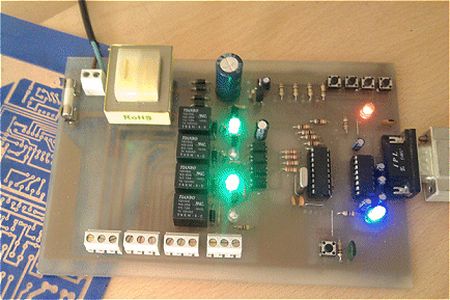
Summary of Rs 232 Relay Control Board using PIC16F84A
This article describes a computer-controlled relay board using PIC16F84A microcontroller technology. It supports manual operation via onboard switches or remote control through a PC interface built with C# and .NET 4. The system features opto-isolation for CPU protection, LED status indicators, and flexible connectivity including USB serial, RF receivers, keypads, or network integration. It is designed to control various external devices like security gates and photographic strobe lights.
Parts used in the Computer Controlled Relay Board:
- PIC Microcontroller (PIC16F84A)
- Relay board with Single pole Double throw relays
- Level converter U1 Max232
- Input switches
- CPU processing unit
- Switching transistors
- Opto-couplers
- LEDs for power and mode indication
- FTDI chips for USB to serial conversion
- Visual CSharp Interface software
Project Summary
Computer Controlled, relay board designed to be either operated manually via switches on the board or nine way Type Connector via PC or laptop. Provision has been made for USB serial adaptor. The Project utilises PIC Micro technology with windows visual interface written C Sharp utilising Dot Net version 4. It can be interfaced to other adapters Keypad adapter (Optional) or RF receiver (Optional) or Via the Net (Optional) Can be adapted to operate other external attachments such as Automatic Security Gates, Slave Flash or multiple Strobe lights for both professional or amateur photographers
Project Description
Can be interfaced to other adapters Keypad adapter (Optional) or RF receiver (Optional) or Via the Net (Optional)
Can be adapted to operate other external attachments such as Automatic Security Gates, Slave Flash or multiple Strobe lights for both professional or amateur photographers
Main Features
Single pole Double throw relays contact rated at 10 amps 14 volts DC
Led Indication for each relay advising Off or On status
Independent manual switching for each relay
Full isolation between relays and CPU via Opto Couplers to eliminate noise, possible destruction of CPU
On Board mains Supply or alternative DC Jack for independent 12 – 14 volts Dc Supply
Mode switch controls manual or Pc control
Mode led advises user of what mode , state of the Board has entered
Can be interfaced to other adapters Keypad adapter (Optional) or RF receiver (Optional) or Via the Net (Optional)
Can be adapted to operate other external attachments such as Automatic Security Gates , Slave Flash or multiple Strobe lights for both professional or amateur photographers
The circuit comprises
A Level converter for conversion of Rs232 signals to TTL level this being U1 Max232
Five input switches , Four of which control the relays for manual operation , One of which is used to detect or switch the state of the Relay PCB to Serial control via the PC or Rs232 cable
A central cpu processing unit which performs the switch detection and subsequent relay triggering , more importantly determines the Rs232 signal input and extracts the commands sent to the board thus operating the relays individually or as a group
In other words the board has the ability to switch all four relays , 3 relays combination of in one single operation This is controlled via the Visual CSharp Interface
Four switching transistors to drive the relays with LED indication for each relay
Four Opto-couplers which in turn drive the relevant relay driver transistors isolating the CPU from the driver transistors This not only prevents possible damage to the CPU but also improves transient electrical noise which can, and does upset the PIC Micro registers due to the induced emf from the Relay coils
Two other led’s which indicate power to the Board , Mode selection in the following order
1: Manual operation
2: Automatic operation in other words serial receive
3: One wire bus to be implemented
Points one and two are again controlled via the Visual interface
Provision has also been made for either USB to serial conversion using FTDI chips .
For more detail: Rs 232 Relay Control Board using PIC16F84A
- How does the board switch between manual and PC control?
A mode switch controls manual or PC control, while an input switch detects the state of the Relay PCB to switch to Serial control. - Can this project operate automatic security gates?
Yes, the board can be adapted to operate other external attachments such as Automatic Security Gates. - What component isolates the CPU from the driver transistors?
Four Opto-couplers drive the relevant relay driver transistors to isolate the CPU. - Does the board support USB connections?
Provision has been made for either USB to serial conversion using FTDI chips. - What software is used for the visual interface?
The project utilizes a Windows visual interface written in C Sharp utilizing Dot Net version 4. - How many relays can be operated individually or as a group?
The board has the ability to switch all four relays or three relays in one single operation. - What happens if there is induced EMF from the relay coils?
The opto-couplers improve transient electrical noise which can upset the PIC Micro registers due to induced EMF. - Can the board be interfaced via the internet?
Yes, it can be interfaced via the Net as an optional feature. - What are the contact ratings for the relays?
The single pole double throw relays have contacts rated at 10 amps and 14 volts DC. - How does the user know the current mode of the board?
A Mode LED advises the user of what mode the state of the Board has entered.