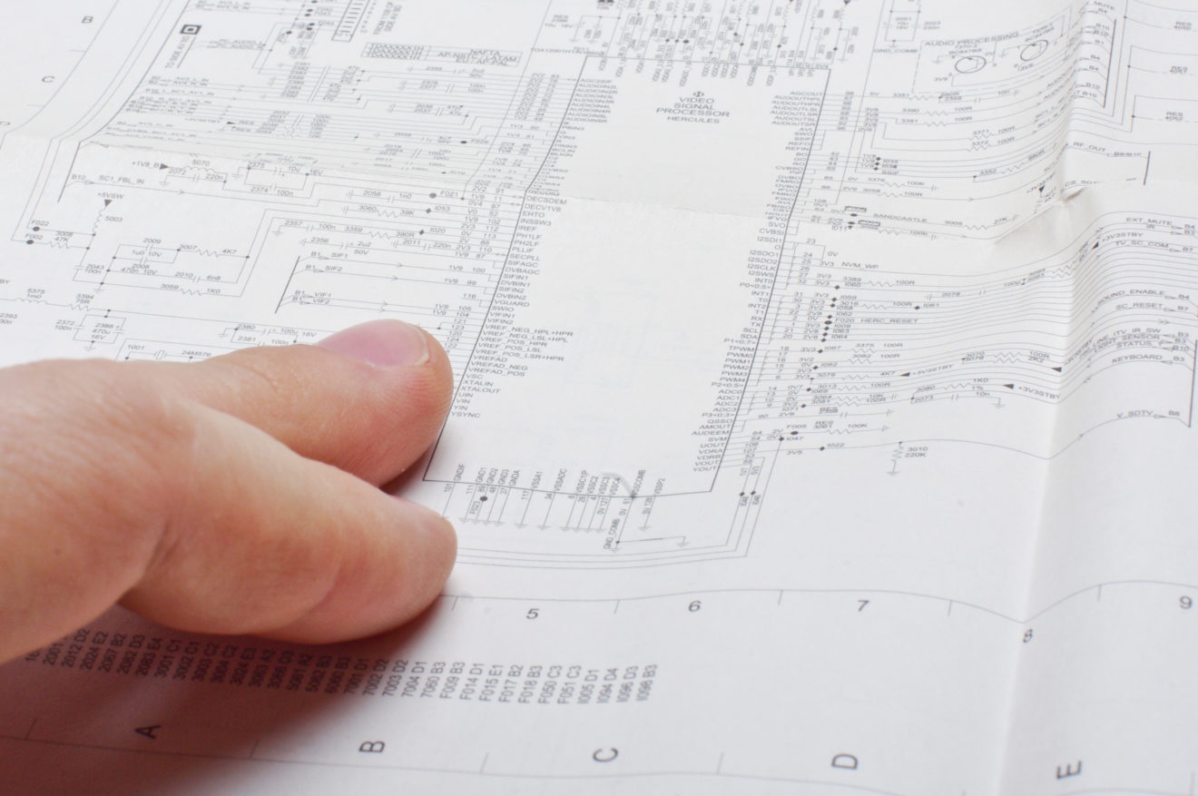
The schematic forms the building block of every electrical circuit, and even if you aren’t designing one yourself, knowing how to read one is invaluable. And with some schematic reading knowledge in hand, you’ll be able to design, build and ultimately troubleshoot your way through your design logic before heading on to your PCB layout.
But how in the world do you go about reading a schematic if it’s your first time? There’s a ton of shapes that might be new to you, all those random lines connecting everything together. Fear not, we’ve got you covered with a surefire way to read your first schematic in Autodesk EAGLE like a pro, in only 3 steps.
Step 1 – Your Building Blocks
Let’s start by going over all the symbols you might find on a typical schematic. While we won’t be covering every possible symbol here, knowing the ones outlined below will make you knowledgeable enough to an average schematic. And for anything you don’t know, remember to refer to a part’s datasheet to find out. Here we go!
Resistors
Resistors are one of the most common building blocks you’ll find in an electrical circuit. Without these guys, those energy efficient LEDs that we’ve come to depend on would never work! The resistor symbol will look different based on if you’re using the US or international standards. For the US, you’ll find a zigzag line connected with two terminals. The international symbol is just a plain rectangle with the same terminal connectors.
for more detail: How to Read Your First Autodesk EAGLE Schematic Like a Pro in 3 Easy Steps

