Summary of PIC12F675 Tutorial 3 : PIC Serial Port
This tutorial explains how to implement a software-based serial transmitter (TX) on the PIC12F675 microcontroller, which lacks a built-in USART. It details configuring I/O ports using TRISIO and GPIO registers, setting communication parameters like 2400 baud and 8 data bits, and utilizing a MAX232 or SP202ECP level translator to interface with a PC via RS232 for data transmission from ADCs or sensors.
Parts used in the PIC Serial Port Project:
- PIC12F675 microcontroller
- MAX232 level translator chip
- SP202ECP level translator chip (alternative)
- 100nF capacitors
- Electrolytic capacitors
- Serial port connector
- Serial cable
- PC
The 12F675 does not have a built in USART that you can use for a PIC serial port so you have to use a software USART which you can download from this page.
Adding a pic serial port connection to the circuit gives you scope for much more interesting projects as you can collect data from the ADC (inputs) or comparator or external infrared receiver module etc. and transmit it to a PC.
This tutorial covers creating the software Transmitter (TX) part of the USART as this is the most useful part of a USART and you don’t really need the receiver unless you want to control the microcontroller via a serial terminal such as Hyperterminal.
Note: The previous two tutorial pages indirectly cover the most important job in using microcontrollers i.e. input and output. Here’s a summary of I/O port usage:
Sidebar
I/O Port usage summary
PORT register : TRISIO – The port direction register.
You can reset bits (low) to define port pins as outputs.
You can set bits (high) to define port pins as inputs.
PORT register : GPIO – The input/output register.
You write to this register to set output pins high or low.
You read from this register to read the current value input pins.
All of these actions were used in the previous two tutorial pages and the all work using bit values:
TRISIO = 0x01; sets bit 0 of TRISIO all the rest zero.
TRISIO = 0x04; sets bit 2 of TRISIO all the rest zero.
GPIO = 0x01; sets bit 0 of GPIO all the rest zero.
GPIO = 0x04; sets bit 2 of GPIO all the rest zero.
Note: In other PIC devices ports are labeled alphabetically and they do not use the GPIO name instead they use the text ‘PORT’. So the first port is labeled PORTA the next PORTB etc. Corresponding port direction registers are TRISA and TRISB. You can use them in exactly the same way as GPIO and TRISIO.
PIC Serial Port : Software TX part
The code for the TX part of the USART is simplified in that it generates 10 bits of serial data with no parity bit.
The basic PIC Serial port configuration for the TX software is:
| Bits per second (BAUD) | 2400 |
| Number of bits | 8 |
| Parity | None |
| Stop bits | 1 |
| Flow control | None |
Note: To review how the RS232 pic serial port works click here.
Since each bit takes 1/2400 seconds the total time to transmit a digit is 4.16ms.
Note: The bit timing won’t be exact as the PIC chip runs at 4MHz but it will be good enough for bench top use.
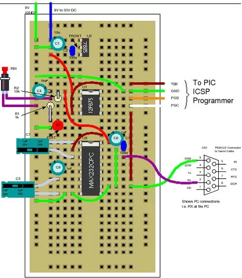
Circuit
The circuit uses the standard MAX232 level translator chip but you could use an SP202ECP which has identical pin out (and is cheaper!) and lets you use 100nF capacitors instead of electrolytic ones.
Connect the ground and transmit output to a serial port connector as shown and to a serial cable from it to the PC and it’s ready to go.
For setting up hyperterminal click here.
For more detail: PIC12F675 Tutorial 3 : PIC Serial Port
- Does the PIC12F675 have a built-in USART?
No, it does not have a built-in USART so you must use a software USART. - What is the primary function of the TRISIO register?
It defines port direction where resetting bits sets pins as outputs and setting bits sets them as inputs. - How many bits are generated by the software TX code?
The code generates 10 bits of serial data with no parity bit. - What are the configured communication settings for the serial port?
The settings are 2400 baud, 8 data bits, no parity, 1 stop bit, and no flow control. - Can the SP202ECP replace the MAX232 chip?
Yes, it has an identical pinout and allows the use of 100nF capacitors instead of electrolytic ones. - What is the approximate time to transmit one digit at 2400 baud?
Each bit takes 1/2400 seconds making the total transmission time 4.16ms per digit. - Which registers are used to set output pins high or low?
You write to the GPIO register to set output pins high or low. - How do other PIC devices label their ports compared to this tutorial?
Other devices use labels like PORTA and PORTB instead of GPIO and use TRISA or TRISB for direction.