Summary of PIC12F1840 + I2C 24FC1025 EEPROM
The article describes using the Microchip 24FC1025 serial I2C EEPROM with a PIC12F1840 microcontroller. It details the chip's 128KB memory split into two banks, its voltage range, and I2C communication protocols including write-protect features and busy-check methods. The project demonstrates storing and retrieving LED rotation patterns to verify data integrity across both memory halves using an MCP23017 expander for output visualization.
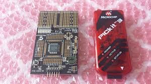
Parts used in the PIC12F1840 + I2C 24FC1025 EEPROM Project:
- Microchip 24FC1025 Serial I2C EEPROM
- PIC12F1840 Microcontroller
- MCP23017 I/O Expander
- LEDs
- VCC Power Supply
The 24FC1025 is a serial I2C EEPROM memory fabricated by microchip, it has 1024Kbits (128KB) of memory space and it is divided in two parts each one of 512Kbits (64KB); the first part goes from address 0x0000 to 0xFFFF and the second part goes from 0x10000 to 0x1FFFF.
Features:
- 128KB of memory space
- 2-Wire serial interface (I2C)
- Compatibility with 100 KHz, 400 KHz and 1.0 MHz clocks
- 2 hardware address bits allowing up to 4 devices on bus
- Hardware Write-Protect
- 128-Byte page write buffer (3ms typical)
- Operating voltage: 1.8V – 5.5V

Pinout PDIP:
Pin function table:
The control byte is composed by the static address (1010 = 0xA) plus the Bank select bit (It is 16th most significant address bit) plus the physical address on A1 and A0 pins (A2 pin cannot be used and it MUST be connected to VCC) and in the end the R/W bit as you can see in the image below:
The I2C sequences to read or write a byte or page from this device are:
After sending a write command for a byte or a page the memory will start the writing cycle, while it is still busy we must not send another command. To know if the memory is busy or not you must send the same control command used for write and check the acknowledge bit, if acknowledge is received memory is not busy, otherwise it is still busy writing the data.
The below flow chart shows what was previously described above:
At this point you can see it is easy to read and write data to this memory so we will follow with an example.
The example consist on generating the values to rotate a led from bit 0 to 7 and backwards (0x01,0x02,0x04,0x08,0x08,0x04,0x02,0x01) and store these values into the first 8 Bytes of the memory (0x00000:0x00007).
Then generate values backwards to the first sequence (0x08,0x04,0x02,0x01,0x01,0x02,0x04,0x08) and save them in the first 8 Bytes of the second half of the memory (0x10000:0x10007).
Next we are going to read each byte of the sequence and show it on a two 8b ports respectively, in the end we must see that one port is a mirror of the other. To do this I use the MCP23017 I/O Expander showing the first sequence on IOA and the other one in IOB.
For more detail: PIC12F1840 + I2C 24FC1025 EEPROM
- How is the 128KB memory space divided?
The memory is divided into two parts of 512Kbits each, where the first part ranges from address 0x0000 to 0xFFFF and the second from 0x10000 to 0x1FFFF. - Can multiple devices be connected on the same bus?
Yes, hardware address bits allow up to 4 devices on the bus. - What happens if you send a command while the memory is writing?
You must not send another command; instead, send the control command again to check the acknowledge bit to see if the memory is still busy. - Which pins can be used for physical addressing?
Only A1 and A0 pins are used for physical addressing; the A2 pin cannot be used and must be connected to VCC. - What is the typical page write buffer size?
The device has a 128-Byte page write buffer with a typical cycle time of 3ms. - Does the device support different clock speeds?
Yes, it is compatible with 100 KHz, 400 KHz, and 1.0 MHz clocks. - What component was used to display the sequences?
An MCP23017 I/O Expander was used to show the first sequence on IOA and the second on IOB. - How do you determine if the memory is busy after a write?
You send the same control command used for writing and check for an acknowledge bit; lack of acknowledgement means it is still busy.