Summary of OSCILLOSCOPE CIRCUIT WITH MAX492 PIC16F877 GRAPHIC LCD
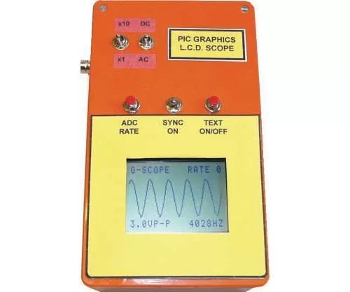
Summary: A PIC16F877-20 (20 MHz) microcontroller-based oscilloscope project using a MAX492 rail-to-rail op amp front end, selectable X1 and X10 inputs, and a 128×64 PG12864 graphic LCD (GLCD) for display. The system runs from a 9 V DC power supply and includes source code in ASM and HEX for firmware.
Parts used in the Oscilloscope Circuit with MAX492:
- PIC16F877-20 microcontroller (20 MHz)
- MAX492 rail-to-rail operational amplifier
- PG12864 128×64 graphic LCD (GLCD)
- Input selector for X1 and X10 probe attenuation
- 5 V indicator circuit (grilimi style)
- 9 V DC power supply
- Circuit assembly components (PCB, connectors, wiring)
- Firmware files (ASM source and HEX codes)
Oscilloscope circuit project pic16f877-20 (20 MHz) microcontroller based on X 1, x 10 entries MAX492 Rail-to-Rail Op Amp input via grilimi 5v indicator as 128 × 64 glcd (PG12864) graphic lcd. Oscilloscope circuit power… Electronics Projects, Oscilloscope Circuit with MAX492 PIC16F877 Graphic LCD “microchip projects, microcontroller projects, pic16f877 projects, “
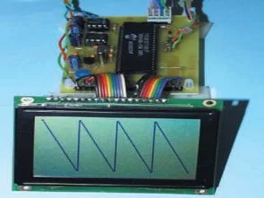
Oscilloscope circuit project pic16f877-20 (20, MHz) microcontroller based on X 1, x 10 entries MAX492 Rail-to-Rail Op Amp input via grilimi 5v indicator as 128 × 64 glcd (PG12864) graphic lcd. Oscilloscope circuit power supply 9v dc
The application schema, the circuit source assemly asm, hex codes for detailed description.
Source: OSCILLOSCOPE CIRCUIT WITH MAX492 Alternative link: oscilloscope-circuit-with-max492-pic16f877-graphic-lcd.RAR
- What microcontroller is used in the project?
The project uses a PIC16F877-20 microcontroller running at 20 MHz. - What op amp is used for the input stage?
The input stage uses a MAX492 rail-to-rail operational amplifier. - What display does the oscilloscope use?
The oscilloscope uses a 128 × 64 PG12864 graphic LCD (GLCD). - What probe attenuation options are provided?
The circuit provides X1 and X10 input selections. - What is the power supply requirement?
The oscilloscope circuit is powered by a 9 V DC supply. - Are firmware sources provided?
Yes, the project includes ASM source code and HEX firmware files. - Does the project include a 5 V indicator?
Yes, it includes a 5 V indicator referred to as grilimi. - Where does the project source come from?
The source is listed as OSCILLOSCOPE CIRCUIT WITH MAX492 with an alternative RAR download link.