Summary of Optocoupler speed-up also reduces power consumption
This article describes a circuit that accelerates optocoupler response by modifying the LED drive side. By adding an NPN transistor emitter follower and a capacitor, the design bypasses a high-value resistor during signal transitions, allowing higher initial current for faster turn-on while enabling a larger steady-state resistor to reduce overall power consumption compared to standard resistive driving.
Parts used in the Optocoupler Speed-Up Circuit:
- Original LED resistor (R1)
- NPN transistor Q1
- Emitter follower configuration
- Low-value emitter resistor (REL)
- High-value emitter resistor (REH)
- Capacitor C
Standard optocoupler speed is limited mainly by the relatively slow response of the phototransistor. This Design Idea adds components to the LED drive side to speed things up.
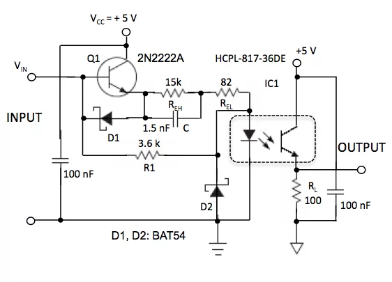
Figure 1 The speed-up circuit not only increases speed of propagation of a rising input signal, but achieves this speed-up at lower power consumption, compared to simplistic driving of the LED through a resistor.
R1 is the original LED resistor, as used before the extra circuitry was added. Here however, its value can be higher, as the turn-on speed is determined mainly by the added circuit. You can thus save power, and also drive the LED with a less powerful driver.
The turn-on speed-up device is an emitter follower, NPN transistor Q1. The emitter follower has its emitter resistor split into a low-value part REL, and a higher-value part REH which is paralleled with capacitor C. At a steep rise of input voltage VIN, the initially uncharged capacitor C temporarily “shorts” REH. Thus, the emitter current flowing through the LED has an increased value of:
For more detail: Optocoupler speed-up also reduces power consumption
- How does this circuit improve optocoupler speed?
The added components increase the propagation speed of rising input signals by momentarily shorting a high-value resistor with a capacitor. - Can this design reduce power consumption?
Yes, it achieves speed-up at lower power consumption compared to simplistic driving through a resistor alone. - What determines the turn-on speed in this setup?
The turn-on speed is determined mainly by the added circuit rather than the original LED resistor value. - Does the original resistor R1 need to be smaller?
No, its value can be higher because the turn-on speed is controlled by the new circuitry. - How does the capacitor affect the circuit during a voltage rise?
The initially uncharged capacitor temporarily shorts the high-value resistor REH when the input voltage rises steeply. - What type of transistor is used as the speed-up device?
An NPN transistor configured as an emitter follower is used. - Why can a less powerful driver be used here?
The ability to use a higher value for R1 allows driving the LED with a less powerful driver.