
Summary of Microcontroller’s based Password Locker
Summary: A simple electronic locker using a Microchip 16F88 microcontroller, a 3x4 keypad, LEDs, pull-up resistors, a 9V supply with MCP1702 regulator, and supporting components. The project explains building the regulator, wiring the keypad to microcontroller pins, and assembling on a non-soldering board (PCB option available). Optional buzzer and multimeter are suggested for testing.
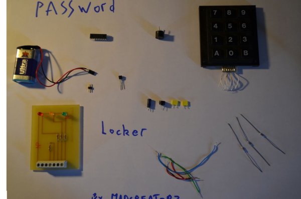
Parts used in the Microcontroller-based Password Locker:
- Microchip 16F88 microcontroller (or any mid-range Microchip MCU)
- Wires
- Green LED
- Red LED
- Third LED for keypad waiting indicator (optional)
- 3x4 Keypad
- 3 pull-up resistors 47 KΩ
- 2 LED resistors (≈ 221 Ω)
- 9 V battery with connector
- MCP1702 voltage regulator
- Capacitors: 100 µF 16V, 10 µF 16V, 100 nF, 100 nF
- Male connector (for power)
- Non-soldering breadboard or PCB
- Programmer for 16F88 (e.g., PICkit or homemade All-PIC programmer)
- Optional: multimeter
- Optional: buzzer for wrong-code alert
Hello Everybody , the goal of this instructables is to learn how to do a simple locker for your room, or anything which need to be safe.
I’ve made it on a non-soldering card but there is the PCB if you want to make it !
Here is the list of differents components that we will need:
– A Microchip microcontroller 16F88 (but all mid-range of microchip will be good)
– Some wires
– 2 LEDs (a green for granted access and a red for denied access, i’m using a pcb with 3 leds the third if when the keypad wait)
– A keypad 3×4 (I’m using an old one but you will find it in every electronics shop)
– 3 Pull-up resistor 47Kohms (needed to make a logical “low”)
– 2 resistors for the Leds (221 ohm will be enough)
– A 9 V battery (with the connector) and a regulator MCP 1702 (from microchip)
– 4 capacitors 100µF 16V / 10µF 16V / 100nF / 100nF
– A way to program the 16f88 ( like http://www.instructables.com/id/All-pic-programmer/ or buy a pickit http://www.microchip.com/stellent/idcplg?IdcService=SS_GET_PAGE&nodeId=1406&dDocName=en010053 )
(The components like the 16F88 and the MCP 1702 can be obtained by asking samples from microchip)
OPTIONAL : A multimeter to test the circuit.
Other components if you want to had a sound when the code is wrong (like a buzzer)
So if you’re ready , Let’s Go !
Step 1: The regulator parts
We need to build the regulator part which will power the microcontroller !
So take the following components :
– MCP 1702 Regulator
– The 4 capacitors (100nF, 100nF , 10µF 16V , 100µF 16V)
– Some little wires
– The male connector
– The battery connector
And finally the non-soldering board (or something similar)
————————————————————————————————————
At first place the MCP on the board, like on the picture,
then put the 4 capacitors between the Vin and the Ground,the Vout and the ground following the schematics.
Now just put the +5V away with a wire, we will connect it to the microcontroller later.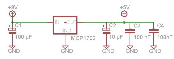
Step 2: The Keypad
Now that we have our power supply for the microcontroller we need to know how to put the keypad.
Keypad can be used with a decoder to know the number of the key pressed but I’ve choosed to do it by programmation, so it’s simple because it’s similar with a simple push button.
As you can see, the keypad is divided in columns (X1 X2 X3) and lines (Y1 Y2 Y3 Y4)
I know that every keypad are different so check the datasheet to see how the wire are soldered.
On this keypad the 7 wires at the bottom correspond to the 4 lines and the 3 column !
Even if yours isn’t the same, the principle is the same !
(Picture 1)
So now we will choose the different Input/output of the microcontroller :
My choice was made for the non-soldering board so I choosed I/0 wich are close,
Pin B7 <-> Y1
Pin B6 <-> Y2
Pin B5 <-> Y3
Pin B4 <-> Y4
Pin A0 <-> X1
Pin A7 <-> X2
Pin A6 <-> X3
Let’s check the picture of the microcontroller. (Picture 2)
So the board will be like that. (Picture 3)
If you didn’t understand how to do it just check this schematic (picture 4)
For more detail: Microcontroller’s based Password Locker
- What microcontroller is used in the project?
The project uses a Microchip 16F88 microcontroller, and other Microchip mid-range MCUs are also suitable. - How is the keypad connected to the microcontroller?
The keypad columns and rows are wired directly to MCU pins; in the example B7-B4 are connected to Y1-Y4 and A0, A7, A6 to X1-X3 respectively. - Do I need a decoder for the keypad?
No, the project scans the keypad by software without a dedicated decoder. - What components form the power regulator?
The MCP1702 regulator plus capacitors (100 nF, 100 nF, 10 µF 16V, 100 µF 16V), battery connector, and male connector form the regulator section. - What resistors are required for pull-ups and LEDs?
Three 47 KΩ pull-up resistors and two LED resistors around 221 Ω are used. - Can I build the project on a non-soldering board?
Yes, the author built it on a non-soldering board and provides a PCB option as well. - How do I program the 16F88?
You can use a PICkit or a homemade All-PIC programmer as referenced in the article. - Is a multimeter necessary?
A multimeter is optional but recommended for testing the circuit.
