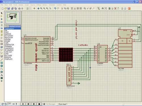
This is aproject to move words on led matrix display we use
1-pic16f628a as microcontroller :cheap,program memory 2k,has internal oscillatror,two ports A,B and alot of things.
2-led matrix 8*8 rows common anode and columns common cathode
3-shift register i use 74ls164 it is simple than 74595 his job is scanning columns activate one at atime
4-uln 2803
every time maximum of eight led work so current=8*(15ma for every led=120ma
shift register can’t sink this much current so we use uln .it can sink current up to 500ma
5-eight resistors 120ohm,pack resistors 10k
The Complete Circuit diagram is Shown
Step 1: Led matrix construction
ledmatrix is shown in pictures to light aspecfic led we apply logic high(1) to anode and logic zero to cathode so we make anode as data source and cathode as scanning (activate cathode of aspecfic column) so we connect anodes(rows) to portb and cathodes to uln and shift register we discuss this later
Step 2: Shift register 74ls164
We must shift register very well to make this project.In general shift register is used to extend microcontroller terminals he take 3 terminals from any port and give us 8 terminals. This shift register is serial input parrel output takes data serially and output it by clock
shift register in simple words consist of :
1-two serial input A,B pin number(1-2)
two serial input is anded so we connect one of them to vcc (1) and other is serial input controlled by pic16f628a.
2-clock pin8
3-eight outputs QA to QH
4-clear pin 9 connect to vcc when connect to ground it clear output pins
5-vcc and ground pin 7 – 14
For more detail: Led matrix project using shift register and pic16f628a micro


