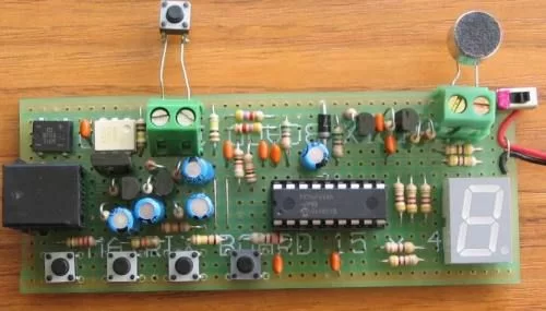
This is the lowest-cost dialing alarm on the market and shows what can be done with a PIC microcontroller. The complete circuit is shown below. You cannot see all the features of this project by looking at the circuit – most of them are contained in the program. So, read on and see what we have included. . .
The programming socket is not on the PC board – it has been added for the time when you want to modify the program and “burn” a new chip.
The arrows on the diagram show the direction of a signal. Outputs RA4 and RA6 produce rail voltage for the stages they are supplying.
Dial Alarm-2 has a single input (although a number of sensors can be placed in parallel on the same input line). The circuit requires a trigger pulse to turn on the Alarm. This is achieved by placing a 1u on the input line and keeping it discharged via two 100k resistors. When the input goes low, the 1u transfers the LOW to the micro and if the input remains LOW, the 1u charges via the second 100k resistor.
The micro executes the program and outputs a low on RB7 to turn on the LED in the opto-coupler and this causes the line to be “picked up” via a high-gain Darlington transistor. The micro then dials two phone numbers and produces a Hee Haw sound to alert the called party of an intrusion. The circuit also has a sensitive microphone with a high-gain amplifier. This is connected to the phone line when the alarm is triggered.
Amplified audio of the room is then passed down the line after the Hee Haw tone. This signal is clear enough to detect conversations and/or movement in the target area and the listener can determine the situation. If the sounds are determined to be family or staff etc, the alarm can be de-activated by pressing any of the buttons on the receiving phone. This will pass a tone down the line and is picked up by the alarm to shut it off. If the first number is not answered within a few seconds, a second number is called and the process is repeated. The two numbers are then called again and the alarm closes down. Simple but brilliant. The flow Diagram for the alarm is shown below:
Use Dial Alarm-2 as a “Back-Up” Alarm
This alarm has been developed in response to a number of recent large robberies reported in the news. Robberies are a constantly increasing crime, but very few are reported, unless they have a “twist.” Recently, the robbers navigated the conventional alarm system and broke into the night safe in the Manager’s office. The haul was quite significant and it’s surprising such a large amount of cash was kept on the premises. The weakest link in most alarm systems are the PIR detectors, used to detect movement. It’s a known fact that they are very easy to foil. It’s so easy we are forbidden to print details of how to do it. But many thieves must be aware of the trick and that’s why a back-up system is essential.
The cheapest back-up system is the use of the phone line. I know what you are going to say. Cutting the telephone line is an easy matter and offers little security. But finding the line in a premises is not very easy and if there are two or more incoming lines, it’s difficult to know which is connected to the dialler. Nothing is infallible, but for a lot less than $50 you can build this project and have a back-up to protect your property.
The other advantage of our design is the “set and forget feature.” The alarm is designed to ring your mobile and if you keep your phone beside you 24 hours a day, you can have this peace of mind, whether you are in your office, factory, holiday house or quietly dining at your favourite restaurant.
You can protect any area where a telephone line can be installed. This includes houses-under- construction and outlying sheds.
Talking Electronics has been producing security devices for more than 15 years and this project is a culmination of those years of experience.
The high-sensitivity amplifier in the alarm is our development and comes from our highly successful Infinity Bug. This device connects to the phone line anywhere in the world and when the number is rung, the infinity bug answers the call and lets you listen in to the activities in the room. It’s just like being there. We have used the same circuit in this project. When it is activated, you can easily work out if it has been triggered by staff, a family member or an intruder. At least it prevents unnecessarily attending 90% of false alarms and offers enormous peace of mind.
The secret lies in the placement of the triggering device. We have provided only one input (trigger input). And there’s a reason for this. The idea is to place the sensor near the target area or on an actual device, near the microphone.
For instance, it you are protecting a house, a thief always goes to the main bedroom and rummages through the drawers and cupboards. In this case a drawer that is never used should be wired with a magnetic switch (reed switch) or a movement detector such as a mercury switch. These switches can be housed in a plastic case for easy screwing to a wall or door and are very reliable in operation. When the drawer is pulled out or the door opened, the switch is activated. If you are protecting a wall safe, the switch is placed near the safe in a clipboard or picture so that when the board or picture is moved, the alarm is activated. If a room is to be monitored, the switch is placed on the door so that when it is opened, the alarm is activated. If other valuables are being protected (such as a VCR, scanner etc) a suggestion is to place a clipboard against the item. The idea is the clipboard has to be moved to get at the “valuables.” The clipboard contains a magnet and the switch is nearby. The clipboard keeps the switch open (or closed) and when it is moved, the alarm is activated.
The ideal arrangement is to avoid touching the clipboard, drawer, door or other “prop” during normal activities and this keeps the alarm activated at all times.
Another suitable trigger device is a pressure mat. This is something that can be avoided by “those in the know” and you can monitor an area during your absence. The alarm can be used for other things too. You can determine when your business premises are opened up in the morning by placing a pressure mat or reed switch on a door. The same can apply to a particular room in your establishment.
The purpose of this article is not only to produce the worlds smallest dialling alarm but also show you how the program runs so you can modify any of the routines to suit your own particular requirements.
The program can be re-written to dial only one number for two rings then hang up, or three rings, then again after 2 minutes or any combination to suit your requirements. Many mobile phones identify the caller on the display and you can keep track of the exact time of arrival and departure of different personnel.
The alarm can be programmed to monitor machinery and dial your mobile when a breakdown occurs. It can monitor water level or even your mail box. The possibilities are unlimited and it’s just a matter of modifying the program to suit your own needs.
But before you change any of the program you have to understand what the program does and be capable of changing the instructions without upsetting the operation of the alarm.
Remember: A little knowledge is a dangerous thing. Before doing any re-writing of the program you need to read our notes on programming and carry out one small modification at a time.
This is really a very advanced project. The fact that is looks simple is the power of the microcontroller. It’s taking the place of at least 10 chips in a normal alarm.
Timing and DTMF tones have all been converted to instructions of a program. And the advantage of a program is the simplicity of alteration. A time-interval can be changed or a phone number altered with a few lines of code. Even new features can be added without the need for additional hardware. This project uses the PIC16F628A to its maximum and shows what can be done with a PIC microcontroller.
You can program a new number or change a number at any time by using the 4 buttons. The number is stored in EEPROM so it will not be lost when the power is removed.
Before we go any further we must state that this project cannot be connected to the public telephone system. Only approved devices can be connected to the Public Phone System and any experimental device must be approved for experimentation and connected via a “telephone Line Separating Device.” These are available from Altronic Imports for approx $100.
This is unfortunately the case and when we discuss connecting the project “to the line,” we are referring to an experimental telephone system such as the one we have put together at Talking Electronics, to test and develop projects such as these.
See the section “Testing The Project” for more details of the Test Circuit. It consists of 27v derived from 9v batteries, a 12v relay, a telephone and a socket, all in series. The 12v relay is included to limit the current.
Dial Alarm-2 is not isolated from the phone line nor does it have any spike protection. Normal phones has 5,000v isolation The maximum input rejection of Dial Alarm-2 is 125v made up of 80v via the collector-emitter of the BD679 transistor and 45v via the collector-emitter of the BC547 transistor. The “ring-voltage” can be as high as 120v and the transistors are just at the point of zenering. They may clip the ring voltage if it exceeds 130v.
For more detail: Dialing Alarm using PIC16F628 Microcontroller