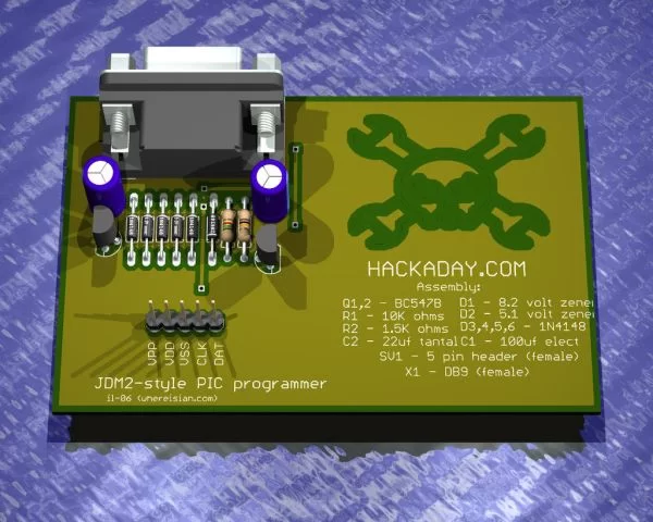
Business Card PIC Programmer
This was my entry for the Hack A Day business card size circuit contest. I just zipped up the files and put them on my website. I’m posting it here because all the other entries seem to be on a blog for easy access. Hopefully this will make the project more accessible and reduce the load on my server.
The attached archive is the contest entry as it was on my server, minus the images. The text is taken from the included document.
This PIC/EEPROM programmer is so simple and small it fits on a business card with enough room left for assembly instructions…
Project:
Simple JDM2 style PIC ICSP programmer (on a business card).
- all through hole
- less than 2USD worth of parts (in 1s and 2s!)
- easy single sided construction at home (with 3 jumpers)
- enough room left for assembly instructions
- extra space on the back for even more business-cardy goodness
- also programs/reads serial EEPROMS
Skill level:
Easy/beginner.
Assembly time:
About an hour.
Step 1
Description
Anyone can build this simple programmer and learn about PIC microcontrollers. The JDM2 programmer is super simple (about 10 parts), but programs a huge variety of PICS and serial EEPROMs. I’ve programmed everything from an 8 pin 12F629 to a new 18F4550 USB PIC with the JDM2. This programmer has an ICSP interface, meaning it can program PICs and read EEPROMs while they are attached to a circuit board. Start your hacking!
The PCB can be made single sided (with three jumper wires), but a two layer design makes assembly even easier. All the traces are nice and fat for easy toner-transfer or photo-process at home.
The JDM2 design is quite old, the original JDM2 circuit can be found here:
http://www.jdm.homepage.dk/newpic.htm
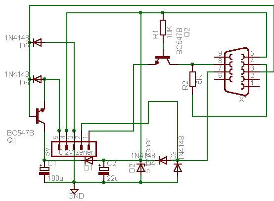
This design stays true to the old schematic, but the diode numbering now starts at 1, rather than 2.
Step 2
Parts
Part Value Description
C1 100uF/16 volt electrolytic capacitor
C2 22uF/16 volt tantalum capacitor
D1 8.2V zener diode
D2 5.1V zener diode
D3,4,5,6 1N4148 diode
Q1,2 BC547B transistor-npn
R1 10K resistor
R2 1.5K resistor
SV1 5 pin header pin header (or female pin header, you choose)
X1 DB9 female serial connector
Step 3
Assembly #1
Don’t forget to begin with the jumper wires if you are using a single sided PCB.
- Solder the diodes and resistors.
- Each diode has a black band that should be oriented in the same direction shown on the board/in the schematic.
- Just solder in the resistors, no special orientation required.


