PIC16F84 speed calculation[clear][clear] circuit 16f84 based on the software assembly-crafted in the speed measurement as a sensor LDR used sensors aralara of the object in the transition delay by calculating the display on the instantaneous speed writes pic assembly… Electronics Projects, Amphometer Circuit PIC16F84 Measure the Speed “microchip projects, microcontroller projects, pic assembly example, pic16f84 projects,
PIC16F84 speed calculation circuit 16f84 based on the software assembly-crafted in the speed measurement as a sensor LDR used sensors aralara of the object in the transition delay by calculating the display on the instantaneous speed writes pic assembly asm code and protel prepared by the printed circuit board files available
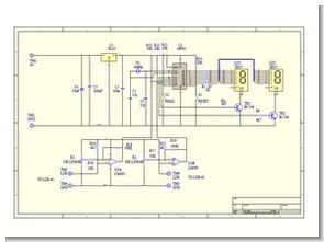
THIS IS THE CIRCUIT FOR THE AMPHOMETER
AMPHOMETER PROJECT
This project is used to measure the speed of a passing vehicle. Usually, this is accomplished by having two rubber strips across the road which operate mechanical switches when driven over. The time it takes for the two switches to operate is used to determine the vehicles speed. A slightly different approach is used here. Two Light Dependant Resistors (LDR’s) are used fo the sensors. As the vehicle passes over the top of these devices, the circuit detects the change in light level. A PIC 16F84 then calculates the speed from the time difference.
The circuit is quite simple. Two comparators are used to sense the change in voltage that is produced when the light level changes on the LDR’s. Two potentiometers are used to adjust the light level threshold that will change the output state of the comparators. When the outputs change, the PIC detects this and calculates the speed as determined by the time it took for the changes to occur. The result is shown on a two digit multiplexed display. The result is also stored into EEPROM for later use if need be.
If the ‘READ’ button is pressed when the unit is first turned on, the displays will show the state of the comparators. ‘S’ for sunny, and ‘C’ for cloudy. Adjust the two pots so that the displays are just on the verge of changing from ‘S’ to ‘C’. The unit is now ready for use.
Turn the power on and press the ‘RESET’ key. The unit will be waiting for the comparator change. When both comparators change, the PIC will display the speed result. If power is turned off, then after it is restored, the last reading is always available by pressing the ‘READ’ key. For the unit to work properly, the sensors must be placed two metres apart. These sensors were made out of pieces of perspex about 10cm square with 4mm holes drilled in the centers. The LDR’s were mounted in these holes with the wires secured on the back face.
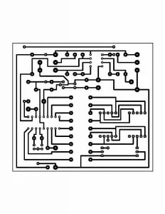
Amphometer Circuit PIC16F84 Measure the Speed schematic protel pcb and assembly source code files:
FILE DOWNLOAD LINK LIST (in TXT format): LINKS-5374.zip