Summary of Automatic door opener with PIC12C508 Circuit
This article describes a PIC microcontroller-based circuit for operating electric strikes or electromagnetic door locks. It features automatic operation via a doorbell, manual button control, and programmable timer delays. A two-color LED indicates system states like auto mode, manual activation, or active timers. Users can program delay durations by entering hexadecimal values through button presses. The project uses a Microchip PIC12C508 chip (or 16F84 for development) with a 78L05 voltage regulator and specific capacitor placements for stability.
Parts used in the Automatic Door Opener:
- PIC12C508 microcontroller
- 16F84 microcontroller (for development)
- Microchip MPLAB development environment
- Two-color green-red LED
- Break-on-push button
- Switch (SW)
- Door relay
- Electric strike or electromagnetic lock
- 78L05 voltage regulator
- 100 nF capacitors
- 100 uF capacitor
Description
This circuit can be used to operate an electric strike or an electromagnetic lock on a door. It is not the door being opened/closed, but a small electromagnetic strike which unlocks the door. The opener has the following features currently programmed in software:
- automatic operation when a guest pushes the doorbell, the strike is operated immediately – can be set by a switch (SW)
- manual remote operation – by pushing a button (BUTTON), the strike is operated immediately
- timer delayed operation by pushing the same button longer than 500 ms – the strike is operated after a pre-set time
- programmable timer delays for relay operating time and delay before timer opening
- two-color LED display shows current state

Usage
After power-on the circuit will be operating and the display LED will be constant RED when the auto switch is in OFF state and will be slowly changing between red and green when the switch is in AUTO state. Shortly pushing the BUTTON will operate the door relay for about 3 seconds (this delay can be reprogrammed). Holding down the PUSH button for a bit longer will operate the door relay after about 20 seconds. This timer delay is also reprogrammable. The display LED lights in constant YELLOW while the delay timer is running.
Delay Programming
WARNING: entering inappropriate codes for the timers will result in strange operation (too long/short delays) and you may have to break the power for the device to reset and start again.
To enter the delay programming mode, hold down the BUTTON and change the state of the SWITCH. The LED display will turn OFF until the release of the BUTTON. In this mode the software reads the values for the two timers in the form of 4 hex numbers. The first two numbers make up an 8-bit value for the timer of the door opening time and the second two numbers make up an 8-bit value for the delay timer. The values are given in a rough 10 ms unit.
- entered digits: D1 D2 D3 D4
- door opening time: D1*16+D2
- opening delay time: D3*16+D4
- to program 3 seconds opening time and 20 seconds delay time you would enter digits 30c8 (3,0,12,8)
- to return to the hard-coded original delay times, break the power to the device for a few seconds.
Entering digits: press the BUTTON the number of times the digit you want to enter. Eg. if you want to enter digit 8, press the button eight times. To finish entering a digit, wait for about 1 second and the LED color will blink, indicating that the code is stored and you can proceed entering the next digit (if there are more). Not pushing the button for 1 second in this mode will store the digit 0 and proceed with a LED blink. After all 4 digits are stored the program will restart with the new values.
Software
the software for the microcontroller is available in source format. It is developed under the Microchip MPLAB development environment, and you will need it or some other PIC compiler to build the object code for the device. If you program the object code, check the fuse settings and make sure that all the I/O pins are programmed to be I/O lines and not OSC or MCLR. In the beginning of the source you find a #define line which sets the PIC chip under which the code will compile. It is a good idea to develop on a 16F84 device and when everything is working, compile the code for the one-time programmable 12C508.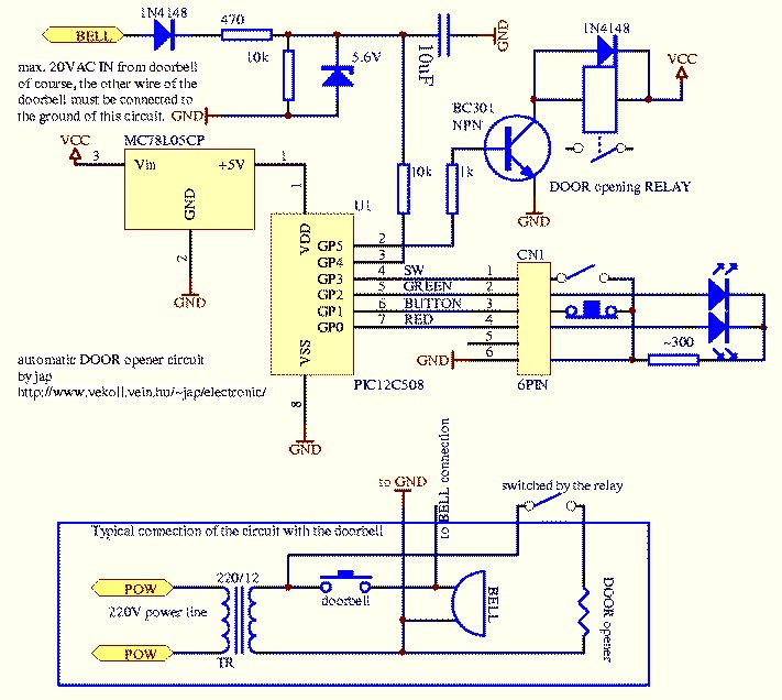
Schematic Diagram
capacitors on the VCC and VDD lines are not shown, but recommended. Place 100 nF close to the PIC pins VCC & VSS, place 100 nF and 100 uF close to the 78L05 pins VCC & GND. The two LED diodes on the scematic are packaged together in a two-color green-red LED with 3 leads. The button is a break-on-push type for fast&sensitive operation.
Note: To report broken links or to submit your projects please send email to Webmaster
For more detail: Automatic door opener with PIC12C508 Circuit
- How does the automatic operation feature work?
The strike operates immediately when a guest pushes the doorbell if the auto switch is set to ON. - Can I manually operate the door lock?
Yes, pushing the button briefly operates the door relay for about 3 seconds. - How do I set a delayed door opening?
Holding down the push button for longer than 500 ms triggers an operation after a pre-set delay of about 20 seconds. - What does the yellow LED indicate?
The display LED lights in constant yellow while the delay timer is running. - How can I change the timer delay values?
Enter programming mode by holding the button and changing the switch state, then input four hex digits representing the time values. - What unit are the timer values measured in?
The entered values are given in rough 10 ms units calculated as D1*16+D2 for opening time and D3*16+D4 for delay time. - Which compiler is needed to build the software?
You need the Microchip MPLAB development environment or another PIC compiler to build the object code. - Where should the 100 nF capacitors be placed?
Place one 100 nF capacitor close to the PIC pins VCC and VSS, and another near the 78L05 pins VCC and GND.