Summary of Ultrasonic Range Finder Circuit AD605 PIC16F876
Summary: An I2C-controlled ultrasonic range finder using a PIC16F876 MCU, AD605 variable-gain amplifier, and 40 kHz transmit/receive transducers. The PIC triggers 16-cycle pulses via a MOSFET-driven transformer to excite the transducer, waits 1 ms, then times/averages return echoes across 255 two-inch intervals using the AD605 output (doubled and rectified) into the PIC ADC, returning distance via I2C in BCD.
Parts used in the Ultrasonic Range Finder:
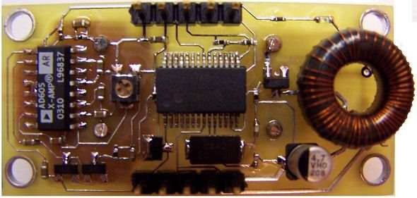
- Microchip PIC16F876 microcontroller
- Analog Devices AD605 Single-Supply Variable Gain Amplifier
- 40 kHz ultrasonic transducers (transmit and receive)
- FDV303NCT N-Channel logic-level MOSFET
- Transducer-matched ferrite core toroidal transformer (Amidon FT-50-J)
- 30 AWG polythermaleze wire
- Clear epoxy (for coating transformer)
- Resistor (approximately 4.32 ohm chosen; 2–10 ohm acceptable)
- 4.7 µF capacitor (across transformer primary to ground)
- Voltage doubler and rectifier circuit (at AD605 output)
- I2C interface wiring and pull-ups (for PIC communication)
Ultrasonic distance measurement, detection circuit pic16f876 microcontroller and ad605 (Dual Low Noise Variable Gain Amplifier singlesupply) integrated circuit diagrams used are C and asm software also Resimlerdede oscilloscope’s measurement. 40kHz ultra sonic transducers used as sensors.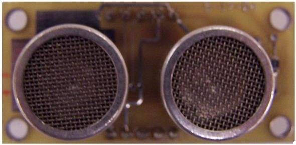
I2C Sonar Ultrasonic Range Finder
In many embedded systems design, it becomes necessary to have the capability of discerning the distance of boundaries or objects without physical contact. Ultrasound can be a very useful tool through which this task can be accomplished with significant accuracy.
The Ultrasonic Range finder utilizes the following primary components.
1. The Microchip PIC16F876 micro-controller
2. An Analog Devices AD605 Single-Supply Variable Gain Amplifier
3. 40KHz Ultrasonic Transducers (Transmit and Receive)
4. “Transducer Matched” ferrite core toroidal Transformer
Ultrasonic Range finder System Operation
The Ultrasonic Range Finder is triggered to return a range sample by communication via I2C interface. After receiving the PIC’s address (which is programmable), a hexadecimal 0x0d, or Carriage Return byte received will cause the module to take a range sample. After triggering a short time period should be delayed to allow the PIC to record the return signal strength for every 2 inches sound travels at room temperature.
When triggered, the PIC processor uses the PWM capability of the Capture/Compare module to generate 16 pulses of approximately 50% duty cycle to an FDV303NCT N-Channel Logic level MOSFET. The micro-controller is then set up to delay 1ms to allow the Ultrasonic Receiver to settle from the Transmitted pulse.
The FDV303NCT drives the primary coil of a t
ransformer. The transformers secondary coil is wound to match the impedance of the Ultrasonic Transducer at 40KHz providing maximum energy transfer efficiency at the Transducers resonant frequency of operation (see notes and calculations below). A ferrite core toroid from Amidon and 30 AWG polythermaleze wire were used. The transformer was coated in clear Epoxy. The primary transformer has only 2 turns and must be isolated from the power supply with a low resistance. Anything from 2 to 10ohms worked fine, a 4.32ohm resistor was chosen. A 4.7uF capacitor was placed across the
primary coil to common/ground. At 50% duty cycle or less, there’s plenty of time for the capacitor to recharge between pulses and provide the energy needed to drive the primary of the coil at full capacity.
After the damping time of 1ms is finished, the processor starts an interrupt driven time delay that is equal to the time it takes sound to travel 2 inches (travel an inch, reflect off an object, travel back an inch) at room temperature 255 times and increment a register for inches. The Receiver Transducers output is connected to an AD605 Amplifier wired for maximum adjustable gain (0dB-96.8dB). The amplifiers output is taken through a voltage doubler circuit and rectified before entering the PIC16F876’s A2D converter. Each returned pulse is averaged with the previous returned pulse to help cancel out noise and the largest pulses corresponding inches register value is recorded as the largest objects distance.
After 255 returned samples have been compar
ed, the inches value is converted from hexadecimal to BCD and ready to be read from the PIC16F876’s I2C Port.
Ultrasonic Range finder calculation and notes
Fο = 1/(2π√LC)
If the capacitance of the transducer is typically 2.4nF (or measured 2.54nF) and the resonant frequency (Fo) is 40KHz, the transducer will have a capacitive-reactance of 1566ohms. The value of the transformers secondary winding was calculated to have the same inductive reactance value of 1566ohms. L is then calculated from the inductive reactance formula XL = 2 πFoL where XL and Fo are the known values. L = 1566ohms/(2π40KHz) to give 6.23mH. The transformer’s primary coil should have only 1 or 2 turns to yield the maximum voltage gain due to the transformer turns ratio.
T1 Characteristics
Amidon Ferrite Toroid
FT-50-J Manganese-Zinc
# Turns – 1000√(6.23mH/AL)
AL = 2710mH/1000 turns from the FT-50-J’s specification
# Turns = 47.97, actual # of turns used was 50 to give the closest mH value of 6.25mH. 30AWG polythermaleze wire was used to wind the transformer.
The Sonar triggering from the received I2C 0x0d byte is shown on SDA (I2C data line) and SCL (O2C clock line). Channel 2 shows the 16 pulses at 40KHz being transmitted at the gate of the FDV303 MOSFET. Channel 1 shows the rectified amplifier output at the input of the PIC’s analog to digital converter. After approximately 15ms the result is read back via the I2C port.
For more detail: Ultrasonic Range Finder Circuit AD605 PIC16F876
- How is the range sample triggered?
The module is triggered via the I2C interface by sending the PIC’s address followed by a 0x0d (Carriage Return) byte. - How does the transmitter generate pulses?
The PIC uses its PWM Capture/Compare module to generate 16 pulses (~50% duty) that drive the FDV303NCT MOSFET gate. - Why is a transformer used between MOSFET and transducer?
The transformer matches the transducer impedance at 40 kHz to maximize energy transfer at the transducer’s resonant frequency. - How long does the system delay after transmission before listening?
The PIC delays 1 ms to allow the receiver to settle before starting measurement timing. - How are return echoes processed before ADC conversion?
The AD605 amplifies the received signal; its output is sent through a voltage doubler and rectifier, then into the PIC’s A2D converter. - How is noise handled when measuring echoes?
Each returned pulse is averaged with the previous returned pulse to help cancel noise, and the largest pulses determine distance. - How many samples are compared before reporting distance?
The processor compares 255 returned samples and records the largest corresponding inches value. - What is the transducer resonant frequency and typical capacitance?
The transducer resonates at 40 kHz and typically has capacitance around 2.4 nF (measured 2.54 nF). - How was the transformer's secondary inductance calculated?
Secondary inductive reactance was set equal to the transducer capacitive reactance (1566 ohms) at 40 kHz, yielding L ≈ 6.23 mH. - How is the measured distance made available?
After conversion to BCD, the PIC16F876 returns the distance via its I2C port.