
Summary of FM Transmitter using MAX4467 & MAX2606
This article describes a simple, low-cost FM transmitter circuit using two Maxim integrated circuits. It functions as a cordless microphone capable of transmitting speech over short ranges. The design features the MAX4467 amplifier and the MAX2606 voltage-controlled oscillator (VCO) to achieve an oscillation frequency around 100 MHz. Key considerations include using a high-Q inductor for L1 and utilizing the shutdown mode of the MAX4467 to save power in battery-operated applications.
Parts used in the FM Transmitter:
- MAX4467 IC
- MAX2606 IC
- Electret microphone
- Inductor L1 (390 nH)
- Silver-plated wire
- Resistor R1
- Capacitor C5
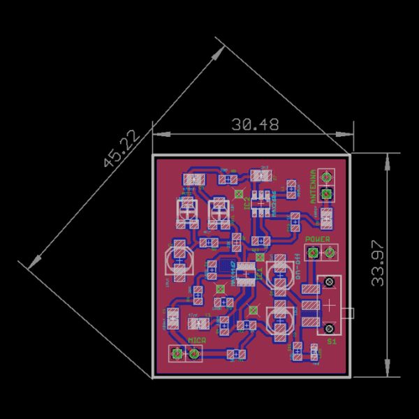
Here is a very simple, inexpensive and interesting project which provides lot of fun to a home experimenter or hobbyist. This simple transmitter can transmit speech over a short range. It can be used as a simple cordless microphone. The circuit uses two integrated circuits from Maxim. IC1 a MAX4467, is an amplifier raising the microphone signal to a level suitable for frequency modulation (FM). IC2 is a voltage-controlled oscillator (VCO) with integrated varactor (a.k.a. varicap diode). Its nominal frequency of oscillation is set by inductor L1. The inductor value 390 nH provides an oscillation frequency of about 100 MHz. For best performance, L1 should be a high-Q component. L1 may consist of 4 turns of silver-plated wire wound around a 10-mm drill bit, and stretched to a length of about 1.5 cm.
The wire diameter can be anything between 26 SWG (0.5 mm) and 20 SWG (1 mm). No core is used. The MAX4467 is a micro-power opamp for low voltage operation and providing 200-kHz gain bandwidth at a supply current of just 24
΅A. When used with an electret microphone, some form of DC bias for the microphone capsule is necessary. The MAX4467 has the ability to turn off the bias to the microphone when the device is in shutdown mode. This can save several hundred micro-amps of supply current, which can be significant in low power applications particularly for battery powered applications like cordless microphones. The MIC-Bias pin provides a switched version of Vcc to the bias components.
Resistor R1 resistor limits the current to the microphone element. The output impedance of the MAX4467 is low and well suited to driving cables over distances up to 50 m. The MAX2606 intermediate-frequency (IF) voltage-controlled oscillators (VCO) has been designed specifically for portable wireless communication systems. The IC comes in a tiny 6-pin SOT23 package. The low-noise VCO features an on-chip varactor and feedback capacitors that eliminate the need for external tuning elements. Only an external inductor (here, L1) is required to set the oscillation frequency and produce a properly operating VCO. To minimize the effects of parasitic elements, which degrade circuit performance, place L1 and C5 close to their respective pins.
For more detail: FM Transmitter using MAX4467 & MAX2606
- What is the primary function of this project?
The project acts as a simple transmitter that can transmit speech over a short range or serve as a cordless microphone. - How is the oscillation frequency set in this circuit?
The nominal frequency is set by the external inductor L1, which provides about 100 MHz with a value of 390 nH. - Does the MAX4467 help reduce power consumption?
Yes, it can turn off the bias to the microphone in shutdown mode to save several hundred micro-amps of supply current. - What is the maximum cable distance supported by the output?
The low output impedance of the MAX4467 is well suited to driving cables over distances up to 50 m. - Can I use any wire diameter for the inductor L1?
The wire diameter can be anything between 26 SWG (0.5 mm) and 20 SWG (1 mm). - Does the MAX2606 require external tuning elements other than the inductor?
No, it features an on-chip varactor and feedback capacitors that eliminate the need for external tuning elements besides the inductor. - Where should L1 and C5 be placed for best performance?
To minimize parasitic effects, L1 and C5 should be placed close to their respective pins.

