Summary of Introduction to Microchip PIC Assembler Language – Part 1
Learning Microchip PIC assembler is valuable for embedded systems; this tutorial focuses on the 8-pin PIC12F683 (nanoWatt, ADC, PWM, comparators, timers) and assumes familiarity with higher-level languages. It explains why hobbyists often use assembly (free full-support tools) and outlines a simple project cycle, circuit using GP0–GP5, and required hardware/software for experiments including digital I/O, ADC, and PWM.
Parts used in the PIC12F683 Assembler Tutorial:
- Microchip PIC12F683 PDIP microcontroller
- Breadboard or prototype board with jumper wires
- 1/4 Watt resistors: 1K (2 pieces)
- 1/4 Watt resistor: 10K (1 piece)
- 1/4 Watt resistor: 330 ohm (1 piece)
- 10K trimpot (1 piece)
- Capacitors: 100nF (1 piece)
- Capacitor: 10nF (1 piece)
- 3mm LED (1 piece)
- 5V regulated power supply or 3 AA/AAA alkaline batteries
- Microchip PICKit2 programmer
- Microchip MPLAB IDE (software)
- PIC12F683 datasheet (downloaded from Microchip)
Learning the assembler language is one of the essential skills that still required in the embedded system, although the major drawback using the assembler language is; its required more learning curve time compared to the higher level language but once you acquainted with one type of microcontroller family such as 8-bit 8 pins Microchip PIC 12F683 then coding with assembly language to other type of PIC microcontroller families will be much easier. I’m choosing the PIC 12F683 type because it’s one of the best 8 pins Microchip PIC microcontroller with nanoWatt technology and supporting advanced peripherals such as 8-bit/16-bit TIMER, ADC (Analog Digital Converter), PWM (Pulse Width Modulation) and Comparator with 2K word of flash.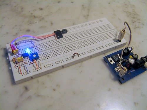
We often hear that one of the reasons we are still coding in the assembly language is the speed and the small HEX code result, but this is not usually true, because some of high optimized industrial standard C compiler can produced more compact code than the average assembler programmer can do for some simple “if” condition statement. Therefore I will add one more important reason why we have to code in assembler language; …we are forced to use the assembly language because most of the average hobbyist could not effort to buy the industrial standard compiler for their project which use a microcontroller type that is not supported or limited supported (e.g. program size limit) by the higher level language free edition compiler; on the contrary all the microcontroller’s manufacture will certainly provide free assembler language compiler that support all of their product types.
But hey… let’s look at the bright side, we are going to learn the core of microcontroller language which gives us more deep understanding of how the microcontroller really works. So before we start with the exciting lessons, I would suggest that you could read the article Beginners AVR Assembler Language Programming 1 posted on this blog for some introduction to what is the assembler language. For the purpose of this tutorial I will assume that you are already familiar with higher level programming language such as C language.
Typical Microcontroller’s based project cycle is shown on the above picture, we will use this simple cycle for practicing our Microchip PIC assembly language skill through various experiments. Ok now let’s take a look at the circuit design for this tutorial: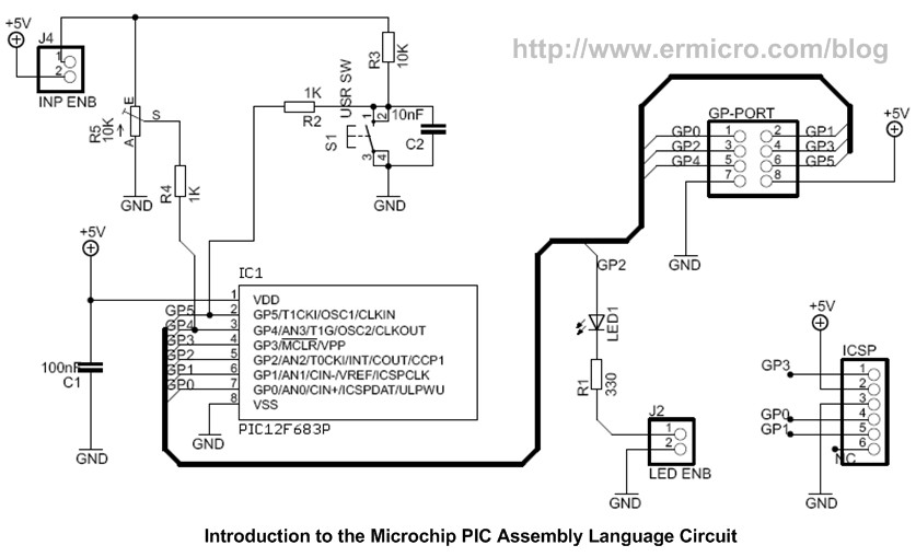
The Microchip PIC 12F683 has 6 general purpose I/O; GP0 to GP5, the above circuit is suitable for learning such as simple digital I/O up to the advanced topics such as using the PIC 12F683 ADC and PWM peripherals.
The Shopping Bag
For this tutorial you will need this following hardware and software:
1. Microchip PIC 12F683 PDIP microcontroller with the datasheet downloaded from Microchip site (www.microchip.com)
2. One breadboard or prototype board with an adequate amount of jumper
3. ¼ Watt resistor: 1K (2), 10K (1), 330 (1), 10K Trimport (1)
4. Capacitor: 100nF (1), 10nF (1)
5. One 3mm LED (Light Emitting Diode)
6. One 5 Volt regulated power supply or you could use 3 AA/AAA size alkaline battery for the project power source
7. Microchip PICKit2 programmer for downloading the HEX code
8. Microchip MPLAB IDE for coding, debugging and compiling the code; downloaded from Microchip site.
For more detail: Introduction to Microchip PIC Assembler Language – Part 1
- Why choose PIC12F683 for learning assembler?
Because it is a compact 8-pin microcontroller with nanoWatt technology and supports peripherals like timers, ADC, PWM, and comparator, making it suitable for varied experiments. - Do I need prior programming experience for this tutorial?
The tutorial assumes you are familiar with higher level programming languages such as C. - What hardware is required for the tutorial?
Required hardware includes PIC12F683, breadboard, resistors, trimpot, capacitors, LED, power supply or batteries, and a PICKit2 programmer. - What software do I need to code and program the PIC?
Microchip MPLAB IDE for coding, debugging and compiling, and the PIC12F683 datasheet from Microchip. - Can I power the project with batteries?
Yes, you can use a 5V regulated supply or 3 AA/AAA alkaline batteries as the power source. - Why use assembler instead of a higher level language?
The article notes assembler is free and fully supported for all device types, which helps hobbyists who cannot afford industrial compilers or face size limits on free compilers. - Will learning assembler help with other PIC families?
Yes, becoming familiar with one microcontroller family makes coding assembly for other PIC families easier. - What I/O does the PIC12F683 provide for experiments?
It provides 6 general purpose I/O pins named GP0 to GP5 for digital I/O and peripheral use.