


Summary of 3x3x3 LED Cube using PIC16F690 microcontroller
This article details a DIY 3x3x3 LED cube project controlled by a PIC16F690 microcontroller. The cube uses multiplexing to illuminate layers rapidly, creating a full-light illusion. Construction involves drilling holes in wood to arrange LEDs, soldering cathodes within layers and anodes between stacked layers. The project includes assembly code (.asm) for the PIC and VB.NET software for designing custom patterns that export as .asm files.Parts used in the 3x3x3 LED Cube:
- PIC16F690 microcontroller
- 27 LEDs (arranged in 3x3x3 configuration)
- Wood piece (for mounting and drilling holes)
- VB.NET software (for pattern creation)
- .asm file (assembly code for the PIC)
- Soldering materials (for connecting legs)
3x3x3 LED Cube
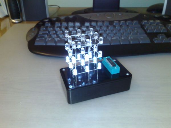
Here is my 3x3x3 LED Cube project. It runs using a PIC16F690. Along with the brief explanation of how to make it, I have also included the .asm file for the PIC and a piece of software written in VB.NET that you can create your own LED patterns. These can be exported as .asm files and put into the main .asm code.
Building
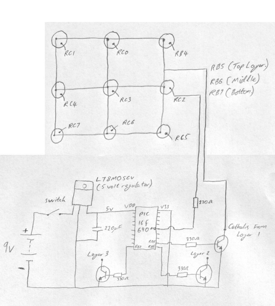
Each layer of 9 LEDS are connected with all of the cathodes together. The cube is multiplexed, meaning that only one layer is on at any one time. It happens so quickly that the whole cube looks like it is illuminated. RB5, RB6 and RB7 controll which layer is being illuminated.
From the picture you can see the connections to the top layer. I have only connected RC2 to show you how the connection should be made, the rest of the LEDs are connected the same way.
The easiest way to connect the LEDs together is to drill 9 holes into a piece of wood (picture 2), then place the LEDs into the holes, bend the legs and solder the cathodes together. After 3 of these are created, simple stack them and solder the anodes together. You should end up with 9 anodes and 3 common cathodes to connect to you circuit.
For more detail: 3x3x3 LED Cube using PIC16F690 microcontroller
Quick Solutions to Questions related to 3x3x3 LED Cube:
-
What microcontroller is used in this LED cube project?
The project runs using a PIC16F690 microcontroller. -
How are the LED layers connected?
Each layer of 9 LEDs has all cathodes connected together. -
Which pins control which layer is illuminated?
RB5, RB6, and RB7 control which layer is being illuminated. -
How does the cube appear illuminated if only one layer is on at a time?
The cube is multiplexed so quickly that the whole cube looks like it is illuminated. -
What is the easiest way to connect the LEDs together according to the text?
Drill 9 holes into a piece of wood, place LEDs in holes, bend legs, and solder cathodes together. -
Can users create their own LED patterns for this project?
Yes, there is a piece of software written in VB.NET to create your own LED patterns. -
How are custom patterns added to the main code?
Patterns created in the software can be exported as .asm files and put into the main .asm code. -
What specific connection is shown in the picture for the top layer?
The picture shows the connection to RC2 to demonstrate how connections should be made.
Related projects
Air Sampler using PIC16F690 microcontroller
Do you ever wonder what is in the air you breathe? Or maybe you have hay fever and want to know what...
LCD & Display Projects · PIC16F690LCD Module Control over IR Link using PIC16F690
Recently I got my hands on a couple of HSDL-1100 based IR transceivers and a KS070B LCD display module. This was a...
LED Projects · PIC16F6908×8 LED matrix using PIC16F690 microcontroller
8x8 LED matrix This instructable will show you how to make a 8x8 LED matrix in witch you can control evry single...
Communication & Interfacing · PIC18F4520CAN FD Node based on a PIC18 Microcontroller
The introduction sets the stage for an embedded systems project that involves developing a Embedded C CAN FD project using the MCP2517FD...
Communication & InterfacingLAN9662 Gigabit Switch: Optimized for Industrial Ethernet
Introduction It should come as little surprise therefore that one element of what is now more commonly referred to in some circles...
Communication & InterfacingPIC Microcontroller: Fundamentals & Applications for Students
Introduction Microcontrollers are the key components in the embedded systems market. A variety of embedded systems was formed and developed after the...

Ibrar Ayyub
I am an experienced technical writer holding a Master's degree in computer science from BZU Multan, Pakistan University. With a background spanning various industries, particularly in home automation and engineering, I have honed my skills in crafting clear and concise content. Proficient in leveraging infographics and diagrams, I strive to simplify complex concepts for readers. My strength lies in thorough...