These cheap RF modules usually come in a pair, with one transmitter and one receiver. A pair can be bought on ebay for as cheap as $4, and even as cheap as $2 a pair if you buy 10 pairs.
Much of the information on the internet from people’s projects is sketchy and not very comprehensive. I test these modules out, and show how to get good reliable serial comms direct from USART -> USART, and I also show how to greatly speed up the data rate and reliability by using an alternative bit encoding system.
Pinouts
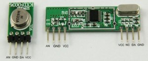
My cheap Ebay modules had this pinout;
Another popular brand (slightly more sophisticated) has this pinout;
But all of these cheap type modules fit these 3 basic pin functions (plus antenna);
Transmitter;
Vcc (power+) 3v to 12v (works fine on 5v)
Gnd (ground-)
Data In (accepts logic level digital data, HI = transmitting carrier)
Receiver;
Vcc (power+) 5v (some may work on 3.3v)
Gnd (ground-)
Data Out (logic level digital data, HI = carrier present)
Data and transmission
This is very simple. When the transmitter data pin is LO, the transmitter is off, and draws less than 1uA. (Mine drew 200 nA from the 5v supply when off). When the transmitter data pin is HI, it is transmitting solid 433 or 315 MHz carrier wave, and with a 5v supply my transmitter drew about 12mA when transmitting continuous carrier.
The transmitter can be run from a higher voltage (like 12v) which increases the transmitting power and range. My tests showed a 5v supply was plenty, even for 20 metres range through multiple house walls. The transmitter is very crude, and all it does is make an RF carrier wave whenever its data input is HI.
The receiver (when powered up) will crank up its gain untl it starts to receive something. If no transmitter is working, the receiver will receive some static. If a modulated carrier (a carrier wave which is turning on and off) is received, the receiver will reduce its gain to remove lesser signals, and ideally will then output the same modulated digital data as that which is controlling the transmitter.
It’s important to know that the receiver takes a bit of time to adjust its gain, so any “packet” of data transmitted should start with a “preamble” before the main data and the receiver will then have time to self-adjust its gain before the important data starts.
Testing the RF modules!
I ran both modules from separate regulated +5v DC supplies, and also attached 173mm vertical “whip” style antennas. (They were 433.92 MHz modules, so these were “1/4 wave” length antennas). Range was tested from a few metres open air, to about 20 metres through walls, and the range did not seem to influence these tests much. So I assume these test results are fairly typical of normal use.
Frequency and duty cycle testing
I used a digital frequency source with precise frequencies and exactly 50:50 duty cycle, this was used to modulate the transmitter Data IN pin.
I found that as the modulating frequency got higher the received duty cycle was corrumpted, with the HI portion of the duty getting smaller;
Freq      Received HI Duty
50 Hz     49%
200 Hz    49%
500 Hz    48%
1 kHz     47%
2 kHz     43%
5 kHz     37%
10 kHz    26%
12 kHz    20-25%
16 kHz    bad!
This is very important for modulating the data, because if trying to use a higher datarate the HI periods will become shorter and most serial protocols like USART serial or manchester encoded serial will fail. This is why these modules are normally only good for 1200 baud serial, or maybe handle 2400 baud serial if everything is perfect (like high signal strength).
Above you can see scope results of the receiver output from 3 different frequency tests, pasted into one picture. All three of these signals was transmitted with exactly 50:50 duty going into the transmitter Data IN pin.
At 1kHz the 50:50 duty of the original waveform into the transmitter is ALMOST preserved, and comes out reliable at about 47% duty.
But the 5kHz and 10kHz are much worse! At 10kHz you can see the pulse widths are very narrow and also noise/gain issues etc make each pulse a different width. The receiver is struggling to capture these short (50uS) pulses.
Trying to fix the duty cycle at the transmitter
Next I adjusted the duty cycle at the transmitter, injecting a digital signal still at 10 kHz, but now with 85% HI and 15% LO duty.
This had only a small effect! Below you can see the signal out of the receiver, the received duty was improved slightly to about 36%, but remember this was transmitted at 85% Hi duty!
Obviously it is a receiver issue, that is reducing pulse width at higher frequencies.
One thing that that WAS improved by transmitting with 10 kHz 85% duty (85uS HI pulses), was that the received pulses were more uniform in width and looked more reliable. That is good to know. 🙂
Simple comms, USART to USART
This was the next thing I tested. Knowing the modulated data was reasonably preserved at 1 kHz, I tried a baudrate of 1200 baud direct from the PIC USART TX pin to the Transmitter Data IN pin.
Plenty of people have done this on the internet with BASIC Stamps and Arduinos etc, so this is the easiest way to get RF comms from a microcontroller to another microcontroller, or from a microcontroller to a PC.
Above shows my simple setup for serial transmission from PIC, to be recieved with my PC.
The only change to the modules was adding a 10uF 25v tantalum cap across the power pins (VCC to GND) on both modules. The transmitter was connected direct to my EasyPIC6 development PCB, and was driven from the PIC USART TX output pin.
The receiver was plugged direct into a cheap USB-TTL Serial adapter (also bought from ebay for a couple of bucks). Three wires were connected; VCC, GND and RX. This also powers the receiver module at 5v from the USB port, handy! This setup is all that is required to send serial data from the PIC to a PC (and be received in the PC using any serial program like Hyperterminal).
Testing serial data; PIC to PC
Set up for 1200 baud, the PIC USART takes about 8.3mS to send a byte. I programmed the PIC to repeat a byte every 12mS, giving a small pause (of approx 4 bits) between bytes sent. Because the PIC USART data out is “typical TTL” type, the default state is HI, so the transmitter is running between bytes (during the extra 4 HI bits between each serial byte). This extra transmit ON time helps to set the receiver gain.
For more detail: How to do serial comms using the cheap RF 433/315 MHz modules