
Summary of USE INPUT OUTPUT PORTS OF PIC18F452 MICROCONTROLLER
This article guides users in writing C code for a PIC microcontroller to read analog input values using the MPLAB X IDE and XC8 compiler. It details hardware setup, project configuration, and specific code implementation to convert analog signals into LED outputs based on voltage thresholds.
Parts used in the PIC Analog Input Reader:
- PICkit programmer
- PIC microcontroller (specifically PIC18F452 or PIC16F1827)
- Some LEDs
- Resistors (to limit current sent to LEDs)
- Sensor producing an analog output (like a potentiometer)
- MPLAB X IDE software
- XC8 Compiler
- MPLAB Code Configurator (MCC) Plugin
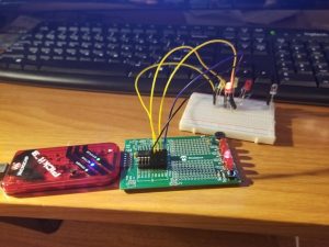
This guide hopefully will show you how to write C code that will allow you to read in an analog input (AI) value to your PIC microcontroller. I am using a PICkit 3 programmer with a PICkit 2 18-pin demo board. The microcontroller is a PIC1827, but the ideas discussed in this article will be applicable to many other PICs as well.
Step 1: Initial Requirments
Hardware Required
– PICkit programmer
– PIC microcontroller
– Some LEDs
– Some resistors (to limit the current sent to the LEDs)
– Sensor that produces an analog output (like a potentiometer)
Software Required
– MPLAB X IDE
– XC8 Compiler (this is because we are writing the program in C)
Download it here if you don’t have it already
– MPLAB Code Configurator (MCC) Plugin
Plugin Setup details found here
Step 2: MPLAB X Project Setup
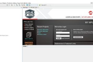
We want to create a new project in the MPLAB IDE.
– Open MPLAB X IDE
– File->New Project
- Category: = Microchip embedded and Projects: = Standalone Project
- Select your device from the dropdown list (mine is a PIC16F1827 for example)
- Debug Header = None
- Select your tool (I selected PICkit 3)
- Select Compiler (We will be using XC8)
- Select a project name+file location then click finish
Assuming you are using a PICkit programmer, you then have the option to power the microcontroller from it.
- Right click the project and select properties
- Select your PICkit programmer on the left hand side
- Select Power from the the dropdown menu
- check the power circuit from PICkit x box and set the voltage level to 3.375
- Press ok
It’s now time to open the code configurator (MCC)
- Click Generate to compile the default main.c file (save the default config file then select yes)
- under the files tab you should now see the main.c file. Open it
Paste the following code
/**
Generated Main Source File
Company: Microchip Technology Inc.
File Name: main.c
Summary: This is the main file generated using PIC10 / PIC12 / PIC16 / PIC18 MCUs
Description: This header file provides implementations for driver APIs for all modules selected in the GUI. Generation Information : Product Revision : PIC10 / PIC12 / PIC16 / PIC18 MCUs – 1.45 Device : PIC16F1827 Driver Version : 2.00 The generated drivers are tested against the following: Compiler : XC8 1.35 MPLAB : MPLAB X 3.40 *
* (c) 2016 Microchip Technology Inc. and its subsidiaries. You may use this software and any derivatives exclusively with Microchip products.
THIS SOFTWARE IS SUPPLIED BY MICROCHIP “AS IS”. NO WARRANTIES, WHETHER EXPRESS, IMPLIED OR STATUTORY, APPLY TO THIS SOFTWARE, INCLUDING ANY IMPLIED WARRANTIES OF NON-INFRINGEMENT, MERCHANTABILITY, AND FITNESS FOR A PARTICULAR PURPOSE, OR ITS INTERACTION WITH MICROCHIP PRODUCTS, COMBINATION WITH ANY OTHER PRODUCTS, OR USE IN ANY APPLICATION.
IN NO EVENT WILL MICROCHIP BE LIABLE FOR ANY INDIRECT, SPECIAL, PUNITIVE, INCIDENTAL OR CONSEQUENTIAL LOSS, DAMAGE, COST OR EXPENSE OF ANY KIND WHATSOEVER RELATED TO THE SOFTWARE, HOWEVER CAUSED, EVEN IF MICROCHIP HAS BEEN ADVISED OF THE POSSIBILITY OR THE DAMAGES ARE FORESEEABLE. TO THE FULLEST EXTENT ALLOWED BY LAW, MICROCHIP’S TOTAL LIABILITY ON ALL CLAIMS IN ANY WAY RELATED TO THIS SOFTWARE WILL NOT EXCEED THE AMOUNT OF FEES, IF ANY, THAT YOU HAVE PAID DIRECTLY TO MICROCHIP FOR THIS SOFTWARE.
MICROCHIP PROVIDES THIS SOFTWARE CONDITIONALLY UPON YOUR ACCEPTANCE OF THESE TERMS. */
#include “mcc_generated_files/mcc.h”
/* Main application *
//prototypes
void initComponents(); //Setup the output pin(s)
void configAI(); //Setup the AI pin(s)
void captureAI(); //Read the AI pin
void setLEDS(uint16_t); //Set LEDs to the AI value
void main(void)
{
// initialize the device
SYSTEM_Initialize();
// When using interrupts, you need to set the Global and Peripheral Interrupt Enable bits
// Use the following macros to:
// Enable the Global Interrupts //INTERRUPT_GlobalInterruptEnable();
// Enable the Peripheral Interrupts //INTERRUPT_PeripheralInterruptEnable();
// Disable the Global Interrupts //INTERRUPT_GlobalInterruptDisable();
// Disable the Peripheral Interrupts //INTERRUPT_PeripheralInterruptDisable();
initComponents(); //Setup Registers
while (1)
{
// Add your application code
captureAI();
__delay_ms(100);
}
}
void initComponents()
{
TRISB = 0x00; //Set PORTB as outputs
PORTB = 0x00; //Clear outputs
configAI();
return;
}
void configAI()
{
//Configure port
TRISA = 0xff; //Set PORTA as inputs
ANSELA = 0X01; //Set RA0 as an AI
//Configure ADC module //b[7] sets right justification, b[6:4] sets CS = FRC,
//b[2]+b[1:0] sets Vss and Vdd as refrences
ADCON1 = 0b11110000;
return;
}
void captureAI()
{
uint8_t delayTime = 20; //20ms acquasition delay
__delay_ms(delayTime);
ADCON0 = 0x01; //Turn ADC on
ADCON0 |= 1 << 1; //set b[1] “go” bit,VAR |= 1 << 3 sets bit 3 fyi
uint8_t doneBit;
do
{
//wait for ADC to complete (go bit switches to 0 automatically when done)
doneBit = (ADCON0 >> 1) & 1;
} while(doneBit); //while go bit is on (AD conversion in progress)
uint16_t result = (ADRESH << 8) | ADRESL; //combine two 8bit values into a 16bit val
setLEDS(result);
ADCON0 = 0x00; //Turn ADC off return;
}
void setLEDS(uint16_t AI)
{
//Light LEDs accordingly
if(AI >= 768) { PORTB = 0x08; }
else if(AI < 768 && AI >= 512 ) { PORTB = 0x04; }
else if(AI < 512 && AI >= 256) { PORTB = 0x02; }
else if(AI < 256 && AI >= 0) { PORTB = 0x01; }
}
/** End of File */
Source: USE INPUT OUTPUT PORTS OF PIC18F452 MICROCONTROLLER
-
What hardware is required to build this project?
You need a PICkit programmer, a PIC microcontroller, some LEDs, resistors to limit current, and a sensor that produces an analog output like a potentiometer. -
Which software tools are necessary for this guide?
The required software includes MPLAB X IDE, the XC8 Compiler, and the MPLAB Code Configurator (MCC) Plugin. -
How do you configure the power supply in MPLAB X?
You must select your PICkit programmer in properties, choose Power from the dropdown, check the box to power the circuit from PICkit, and set the voltage level to 3.375. -
How is the ADC module configured in the code?
The ADC module is configured by setting TRISA as inputs, ANSELA to set RA0 as analog, and setting ADCON1 with specific bits for right justification and references. -
How does the code wait for the ADC conversion to finish?
The code uses a do-while loop that checks the go bit in ADCON0; it continues waiting until the bit switches to 0 automatically when the conversion is done. -
How are the LED states determined based on the input?
The setLEDS function maps the 16-bit result to different PORTB values depending on ranges: 768 or above lights one LED, while lower ranges light others sequentially down to 0. -
Can this method be used with other PIC models?
Yes, although the example uses a PIC1827 or PIC16F1827, the ideas discussed are applicable to many other PICs. -
What is the purpose of the delay in captureAI?
A 20ms acquisition delay is implemented before turning the ADC on to ensure proper sampling time.
