Summary of Bluetooth Controlled Robot using pic microcontroller
This article details an Android and Bluetooth-controlled robot built with a PIC16F877A microcontroller. It features obstacle avoidance using an HC-SR04 ultrasonic sensor, distance display on an LCD, and wireless control via a mobile app. The system uses an L293D motor driver for movement and emits beeps when obstacles are detected within 25 cm, ensuring safe navigation without physical contact.
Parts used in the Android and Bluetooth Controlled Robot:
- PIC16F877A
- L293D IC
- 7805 IC
- 16x2 LCD
- Ultrasonic Sensor HC-SR04
- Crystal 20MHz
- Transistor BC548
- Resistors (10Kx2, 1Kx2)
- Capacitors (33pfx2, 10uF/16V)
- PCB
- DC gear motors (100 rpm x 2)
- Robot frame and wheels
- HC-06 or HC-05 Bluetooth module
- 12V / 1.2Ah rechargeable battery
Today I came up with another engineering project for electronics and communication students, Android and Bluetooth controlled robot using PIC Microcontroller with object detecting capability.
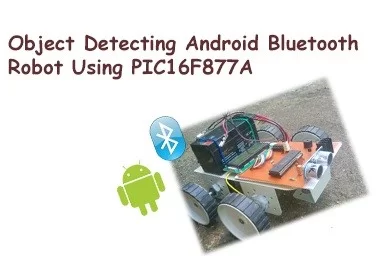
After installing MikroElectron’s Robot Control App from Play Store you should be able to control the robot with your android phone/ tablet over bluetooth signal. The eye catching feature of this project is the ‘objects detection’ capability with the help of Ultrasonic sensor, so you don’t have to worry about the robot hitting any object or wall in front of it. Robot will navigate safely without touching any obstacles. Moreover it will make beep sounds if any obstacle is found and a LCD screen is used to display distance to the specified object.
Speaking about the hardware, I’ve used PIC16F877A to control the robot, ultrasonic sensor will generate ultrasonic pulses to detect objects and calculate the distance, LCD screen to display distance, HC-06 / HC-05 Bluetooth module for communicating to Robot wirelessly.
Well let’s see how to make a mobile robot for your academic project.
Components for Android Robot
- PIC16F877A
- L293D IC
- 7805 IC
- LCD 16×2
- Ultrasonic Sensor HC-SR04
- Crystal 20MHz
- Transistor BC548
- Resistor (10Kx2, 1Kx2)
- Capacitor (33pfx2, 10uF/16V)
- PCB
- DC gear motor (100 rpm x 2)
- Robot frame and wheels
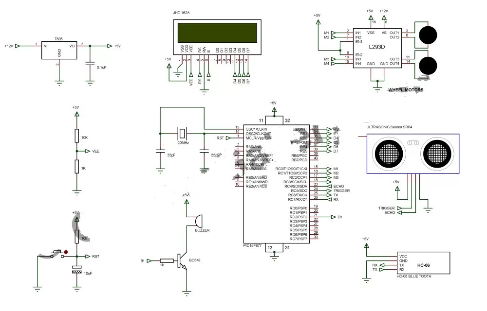
Circuit Diagram of Bluetooth Controlled Robot
Working of Obstacle avoidance robot
For simplicity let’s consider this project having 2 parts- Bluetooth navigation section and object detection section.
- HC-06 / HC-05 Bluetooth module is used to receive data from android based device.
- After pairing (connecting) the Bluetooth module with android phone or tablet, open the application and connect to the paired device HC-06 or HC-05.
- Android application will send letters ‘F’, ‘B’, ‘R’ and ‘L’ to move robot forward, backward, right and left respectively.
- These are received by the Bluetooth receiver, those letters are available in TX pin of HC-06.
- TX pin of Bluetooth module is connected to RX pin (26) of PIC microcontroller, which receives information from the Bluetooth module.
- That information is used as an interrupt to switch between user defined functions that we have specified.
- We have written different functions to perform assigned tasks viz Move forward, backward, turn left and right. These functions will change the values of pins RC0, RC1, RC2 and RC3. Wheel rotations are controlled by these pins.
- Here we are using IC L293D to drive wheel motor, which is capable of driving 2 motors at a time.
Object Detection
- HC-SR04 ultrasonic sensor is used measure the distance between object and robot.
- HC-SR04 ultrasonic sensor has 4 pins- Vcc, Ground, TIRGGER and ECHO.
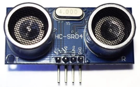
- ECHO is connected to Pin 23 and TIRGGER to Pin 24 of PIC Microcontroller respectively.
- Initially we may trigger the ultrasonic sensor by applying a TRIGGER pulse via Pin 23 of PIC MCU.
- This will initiate the sensor to transmit out 8 cycles of ultrasonic burst at 40 kHz and then it waits for the reflected ultrasonic burs. When the sensor detects ultrasonic from receiver, it will set the ECHO pin to high (5V) and delay for a period (width) which is in proportion to the distance.
- The time difference between transmitted and reflected ultrasonic burst is calculated using TIMER1 module of PIC.
The distance is calculated by the formula

Where,
Speed= Velocity of light.
Time= Time between transmitted and reflected wave.
- The calculated distance is displayed over an LCD display; LCD is driven by PORT B.
- If the distance is less than 25 cms, robot will rotate right 90 degree and produces a beep sound to inform that an object has been found. This will help to avoid objects and acquire safe path.
I have used 12V /1.2Ah rechargeable battery to operate the robot.
- How do I control the robot wirelessly?
You must install MikroElectron's Robot Control App from the Play Store and pair your Android device with the HC-06 or HC-05 Bluetooth module. - What commands does the Android app send to move the robot?
The app sends letters F, B, R, and L to move the robot forward, backward, right, and left respectively. - How does the robot detect objects in its path?
The HC-SR04 ultrasonic sensor generates pulses to measure distance and detects reflected waves to identify obstacles. - What happens if an obstacle is found closer than 25 cm?
The robot rotates right 90 degrees and produces a beep sound to inform the user of the object. - How is the distance to an object displayed?
The calculated distance is shown on an LCD 16x2 screen which is driven by PORT B of the microcontroller. - Which component is used to drive the wheel motors?
The L293D IC is used to drive two DC gear motors simultaneously for wheel rotation. - How is the distance calculation performed technically?
The TIMER1 module of the PIC calculates the time difference between transmitted and reflected ultrasonic bursts to determine distance. - What power source operates this robot?
A 12V / 1.2Ah rechargeable battery is used to operate the entire robot system.