Summary of PWM Signal on Nuvoton N76E003 Microcontroller – LED Dimming using Duty Cycle Control
This tutorial explains using PWM on the Nuvoton N76E003 microcontroller to dim an LED by varying duty cycle while keeping frequency constant. It covers PWM basics, required hardware (N76E003 dev board with onboard test LED, Nu-Link programmer or 5V supply), PWM-capable pins, PWM registers (period PWMPH/PWMPL, six channel duty registers), I/O mode configuration (PxM1/PxM2), and enabling PWM via PIOCON0/PIOCON1.
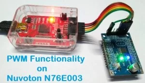
Parts used in the LED Dimming with N76E003:
- Nuvoton N76E003 microcontroller development board
- Onboard Test LED (connected to port 1.4)
- Nu-Link Programmer
- Optional 5V power supply unit
Pulse Width Modulation (PWM) is a commonly used technique in microcontrollers to produce a continuous pulse signal with a defined frequency and duty cycle. In short, PWM is about changing the width of a pulse while the frequency is constant.
A PWM signal is mostly used in controlling a servo motor or brightness of an LED. Also, since microcontrollers can only provide Logic 1 (High) or Logic 0 (Low) on its output pins, it cannot provide a varying analog voltage unless a DAC or Digital to Analog converter is used. In such a case, the microcontroller can be programmed to output a PWM with a varied duty cycle which can then be converted to the varying analog voltage. We have previously used PWM peripheral in many other microcontrollers as well.
- ARM7-LPC2148 PWM Tutorial: Controlling Brightness of LED
- Pulse width Modulation (PWM) using MSP430G2: Controlling Brightness of LED
- Generating PWM using PIC Microcontroller with MPLAB and XC8
- Pulse width Modulation (PWM) in STM32F103C8: Controlling Speed of DC Fan
- Generating PWM signals on GPIO pins of PIC Microcontroller
- Raspberry Pi PWM Tutorial
- PWM Tutorial with ESP32
In this tutorial, we will interface an LED that will be controlled using this PWM signal from the N76E003 microcontroller unit. We will evaluate what kind of hardware setup we require and how we should program our microcontroller. Before that, let’s understand some basics of a PWM Signal.
Basics of PWM Signal
In the below image a constant PWM signal is shown.

The above image is nothing but a constant square wave with the same ON time and the same OFF time. Suppose, the total period of the signal is 1 Second. Thus the on time and off time is 500ms. If an LED is connected across this signal, the LED will turn on for 500ms and turn off for 500ms. Therefore, in perspective view, the LED will lit up with half of the actual brightness if it is turned on to a direct 5V signal without any off time.
Now as shown in the above image, if the duty cycle is changed, the LED will lit up with 25% of actual brightness using the same principle as discussed before. If you want to know more and learn about Pulse Width Modulation (PWM), you can check out the linked article.
Hardware Setup and Requirement
As the requirement of this project is to control LED using PWM. An LED is required to be interfaced with N76E003. Since an LED is available in the N76E003 development board, it will be used in this project. No other components are required.
Not to mention, we need the N76E003 microcontroller based development board as well as the Nu-Link Programmer. An additional 5V power supply unit may be required if the programmer is not used as a power source.
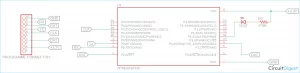
Circuit Diagram for Nuvoton N76E003 Microcontroller LED Dimming
As we can see in the below schematic, the Test LED is available inside the development board and it is connected on port 1.4. On the extreme left, the programming interface connection is shown.
PWM Pins on N76E003 Nuvoton Microcontroller
The N76E003 has 20 pins out of which 10 pins can be used as PWM. The below images is showing the PWM pins highlighted in the red square box.
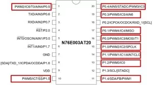
As we can see, the highlighted PWM pins can also be used for other purposes. However, this other purpose of the pins will not be available when the pins are configured for PWM output. Pin 1.4 which is used as a PWM output pin, it’ll lose the other functionality. But, that is not a problem as another functionality is not required for this project.
The reason behind choosing pin 1.4 as an output pin is because the inbuilt Test LED is connected on that pin in the development board, thus we do not require external LEDs. However, in this microcontroller out of 20 pins, 10 pins can be used as a PWM output pin and any other PWM pins can be used for output related purposes.
PWM Registers and Functions in N76E003 Nuvoton Microcontroller
N76E003 uses system clock or Timer 1 overflow divided by a PWM clock with Prescaler selectable from 1/1 ~ 1/128. The PWM period can be set using the 16-bit period register PWMPH and PWMPL register.
The microcontroller has six individual PWM registers that generate six PWM signals called PG0, PG1, PG2, PG3, PG4, and PG5. However, the period is same for each PWM channels because they share the same 16-bit period counter but the duty cycle of each PWM can be different from others as each PWM uses different 16-bit duty cycle register named as {PWM0H, PWM0L},{PWM1H, PWM1L}, {PWM2H, PWM2L},{PWM3H, PWM3L},{PWM4H, PWM4L}, and {PWM5H, PWM5L}. Thus, in N76E003, six PWM outputs can be generated independently with different duty cycles.
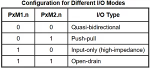
Unlike with other microcontrollers, enabling the PWM does not set the I/O pins into their PWM output automatically. Thus, the user needs to configure the I/O output mode.
So, whatever is required for the application, the first step is to determine or select which one or two or even more than two I/O pins as PWM output. After selecting one, the I/O pins need to be set as Push-Pull mode or Quasi-bidirectional for generating the PWM signal. This can be selected using the PxM1 and PxM2 register. These two registers set the I/O modes where the x stands for the Port number (For example, Port P1.0 the register will be P1M1 and P1M2, for P3.0 it will be P3M1 and P3M2, etc.)
The configuration can be seen in the below image-
Then, the next step is to enable the PWM in that particular I/O pin(s). To do this, the user needs to set the PIOCON0 or PIOCON1 registers. The register is dependent on the pin mapping as PIOCON0 and PIOCON1 control different pins dependent on the PWM signals. The configuration of these two registers can be seen in the below image-
Source: PWM Signal on Nuvoton N76E003 Microcontroller – LED Dimming using Duty Cycle Control
- What is PWM used for in this project?
PWM is used to control LED brightness by changing pulse width (duty cycle) while frequency is constant. - Which pin is the onboard test LED connected to?
The onboard test LED is connected to port 1.4 on the development board. - How many PWM output channels does N76E003 provide?
N76E003 provides six individual PWM channels named PG0 through PG5. - Can each PWM channel have a different duty cycle?
Yes, each PWM channel has its own 16-bit duty cycle registers allowing different duty cycles. - Do PWM channels on N76E003 share the same period?
Yes, all PWM channels share the same 16-bit period counter (PWMPH and PWMPL). - Do I/O pins automatically become PWM outputs when PWM is enabled?
No, enabling PWM does not automatically set pins to PWM output; the I/O mode must be configured manually. - Which registers set the I/O mode for PWM pins?
The PxM1 and PxM2 registers set the I/O mode (Push-Pull or Quasi-bidirectional) for PWM pins. - Which registers enable PWM function on selected pins?
The PIOCON0 and PIOCON1 registers are used to enable PWM function on pins depending on pin mapping.