Pulse Width Modulation (PWM) is a technique in which the width of a pulse is modulated, keeping the time period of the wave constant. Sound Generation with PWM can be achieved by modulating the pulse width to produce audio tones or signals. The ON time and OFF time can have any different values in the wave cycles, but the sum of the ON time and OFF time remains same for the entire cycles. PWM is a digital wave that can be generated using digital circuits which are not capable of generating analog voltages. With the help of the modulation of the width of a pulse in a period of the wave, they can generate any required voltage with the help of a proper filter circuits. The filter circuits are used for generating the voltage corresponding to a modulated wave
This feature of the PWM wave is making use in so many digital systems like DC motor control, audio devices, simple decoration light controls etc. The PIC18F4550 has an inbuilt PWM module which can generate continuous PWM waves. This project explores the PWM module of the PIC18F4550 and tries generating a sine wave with frequency in the audible range and then produce that sound in a Loud Speaker with the help of a filter circuit and Loud Speaker driver circuits.Generating a sine wave has a great deal of significance since the sine wave is the most natural waveform and all other kind of waves can be generated as a combination of sine waves with different frequencies and amplitude. Generating an audible sine wave and producing its sound in a Loud Speaker is the first step towards using the microcontroller in audio applications like media player, announcement system, record and playback etc.
The PIC18F4550 has four PWM output channels and they are P1A, P1B, P1C and P1D. All of them are capable of generating PWM waves at a time. In this project only one of the PWM channels are using. The P1A is the PWM channel in this particular project. This channel is used to generate the PWM waves which are then applied to a filter circuit to generate the sine wave which is described in a previous project on PIC Sine Wave Generation. In this project a driver circuit is designed to generate the sound of that audible sine wave in a Loud Speaker. A simple example of the of waves generated at P1A pin is shown below;
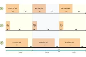
The period of the wave is the sum of the ‘ON time + OFF time’. Duty-cycle is the percentage of time period for which the logic1 voltage exists in a cycle (ON time), starting from the beginning of the cycle.
The PWM is that kind of a wave in which the ON time and OFF time can vary in a cycle but the sum of ‘ON time + OFF time’ remains constant for every cycle.
Period = ON time + OFF time
Duty-cycle = ON time / (ON time + OFF time) = ON time / Period
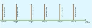
Increasing the Duty-cycle will increase the voltage at the filter device’s output and decreasing the Duty-cycle will decrease the voltage as well. In this particular project the sine wave samples are generated periodically by re-writing the value of the CCPR1 register to vary the Duty-cycle. It is done by generating interrupts periodically with another timer module timer0 and changing the CCPR1 value when the code is inside the timer0’s ISR. It is done as shown in the following figure;
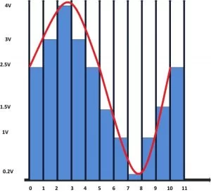
The voltage generated by the PWM wave in the interval between two interrupts will be a constant value and this time period can be called ‘sampling period’. The values of voltage that appears at each sampling period are simply called ‘samples’. The more the number of PWM cycles in a Sampling time, more stable the output voltage will be an example of the sine wave samples is shown following figure in which 10 samples are used to resemble a sine wave. These values when applied to a filter circuit can generate the sine wave at its output by smoothing the step size. The brown line shows the actual sine wave constructed by the filter circuit.
The values that should be assigned to the CCPR1 register to generate such consecutive samples are actually taken from a look-up table. The look-up table with 50 samples which is used in this particular project to generate the sine wave is shown in the following;
Time period calculations:
In this section the calculations for the sampling time, PWM Period, PWM Duty-Cycle, frequency of the sine-wave etc. are calculated and the details of the calculations are available in a previous project on PIC Sine Wave Generation
Sampling time:
In this project the TMR0 is set to zero and the timer0 is configured as an 8 bit timer with pre-scale value 1:2 which gives a sampling time;
Sampling time = 40us
PWM period:
In this particular project the PR2 is written to a very small value so as to generate small time periods and hence to get more number of PWM cycles per sampling period.
PR2 = 22
The PWM Period = 2us
Number of PWM cycles per Sample = 20
Thus the timer0 will generate an interrupt after every 20 PWM cycles.
The frequency of the sine wave = 500 Hz
PWM Duty-cycle:
The Duty-cycle in this particular project is varied according to the look-up table whenever a timer0 interrupt occurs. The maximum Duty-cycle (100%) is 2us only since it is the value of the PWM period, hence
The CCPR1 can be written with any value between 0 and 100
The filter design:
The following figure shows a microcontroller generating PWM wave which is then used to generate the corresponding analog voltage with the help of a filter circuit
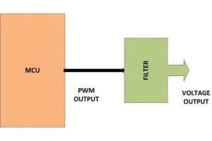
In this particular project the filter circuit is actually an integrator made with a single capacitor. The filter simply integrates the duty cycle of each PWM cycles and hence averages out the voltage in a PWM wave.The integrator is a circuit which has a resistor and a capacitor in series connected across the input and the ground and the analog voltage is obtained across the capacitor as shown in the following figure;
The driver circuit design:
The devices like LED can be directly driven by the PWM pin of the microcontroller, but when it comes to high power consuming devices like Loud Speaker or DC Motor etc. a specially designed driver circuit is necessary due to the following reasons.
The microcontroller is not able to source the required current
High current flow to the load attached to the PWM pin can cause internal drop of voltage inside the I/O pin and hence the PWM voltage level varies.
The filter circuit may not be able to generate the required voltage in such situations.
Making the microcontroller to source that much current may damage the microcontroller permanently.
In short the Load should get enough current and voltage without affecting the functioning of the filter circuit or the microcontroller.
The driver circuit itself consumes some current and hence the current flowing through the driver circuit from the PWM pin should also be limited. This can be done by connecting a high value series resistance with the driver circuit. The following block diagram shows the arrangement of the filter circuit, driver circuit and the load.
Source: How to Generate Sound using PWM with PIC Microcontroller- (Part 22/25)
About The Author
Muhammad Bilal
I am a highly skilled and motivated individual with a Master's degree in Computer Science. I have extensive experience in technical writing and a deep understanding of SEO practices.