This page will show you how to use the TD-CMP modules in a way which fits you most.
Here are the technical specifications of the modules:
- Compass: Resolution: 1° – Accuracy: 3°
- Tilt/Roll: (TD-CMP02 and TD-CMP03 only) Resolution: 2° – Accuracy: 5°
- Temperature: (TD-CMP03 only) Resolution= 1°C/F – Accuracy =1°
- New: Sampling rate: 12,5 to 25 samples/second.
- Easy Tilt/Roll calibration.(TD-CMP02 and TD-CMP03 only)
- Interfaces: I²C, RS232 and mini-USB (as a HID device: PID=0461, VID= 1023)
- Powered by USB bus or an external 5V.
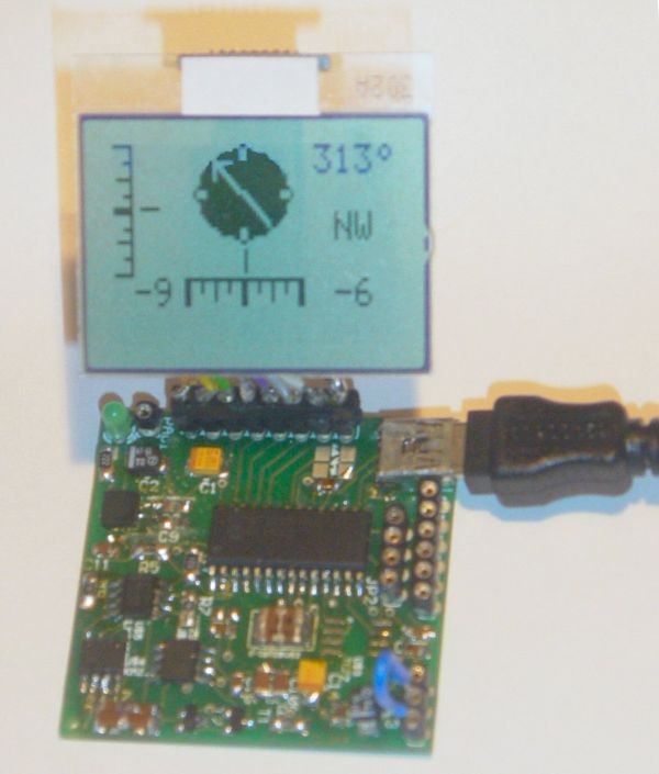
- Direct LCD readout possible. LCD contrast by user.
- Low power LED lights when facing North (angle within 11,25° both left and right from North.)
- USB Windows application (written in C#) available for free download.) Compatible with WinXp/Vista.
- Source code (CCS C and C# .NET) and schematics (Eagle) can be purchased separately.
- Module software is 100% upgradable with a simple bootloader.
- PCB Dimensions: 40 x 41 mm or 1″57 x 1″61, weight: 10 grams.
These assembled modules are available from our online shop.
You may also purchase the bare pcb, a KIT DIY* version and the source code. KIT step-by-step construction guide.
New: compass calibration.
Schematics and pcb diagrams available for download. Last update: November 26, 2009.
DIY* = Do It Yourself
Power Source: JP4: Connect pin 2 to pin 3 to power the module directly from USB. Connect pin 1 to pin 2 when powered externally via JP3, pin 1.
New: Increase sampling speed from 12,5/second to 25/second: connect SPEED1 to SPEED2 (JP3, pin4 to JP3, pin2.)
LCD contrast Adjust: Connect pin 5, JP3 to +5V before powering up. Release when the desired the contrast is reached.
Tilt/Roll Calibration: (TD-CMP02 and TD-CMP03 only):
- First place the module on a completely flat surface, power up.
- Then shortly apply +5V (pin 1, JP2) to ADJUST (pin 5, JP3) Release after 1 second.
- Check readings when applying tilt/roll to the module. Repeat the calibration procedure if necessary. Done.
Compass Calibration: (do not touch the PCB or chips whilst calibrating.)
- First place the module on a completely flat surface, power up, head to North (position as shown in diagram and picture above), then turn the module slowly 360° (make 2-3 full clockwise and/or counter-clockwise spins.)
- Now apply +5V (pin 1, JP2) to ADJUST (pin 5, JP3) Wait for 8-10 seconds; the LED will flash 3 times. Release the ADJUST pin from +5V. Power off and on.
- Check compass readings when heading the module to N, S, E, W. Repeat the calibration procedure if necessary. Done.
Module RESET: apply GND to MCLR pin.
Temperature sensor: (TD-CMP03 only): The external LM335Z sensor connects to JP3 pin 4 and 6. No temperature will be displayed when the sensor is removed.
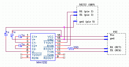
RS232 interface:
JP2 provides the interface to connect to your COM port and hyper terminal. Communications @ 115200 bpS, 8N1.
Use a level converter like the MAX3232 between the TD-CMP module and the pc serial port. See this example.
Also used for bootloading (module software update.) Check under the download section below for the latest version. Bootloading of the HEX-file can be done with Tiny Bootloader 1.91
For more detail: Roll and Temperature sensor applications using PIC18F2550
About The Author
Ibrar Ayyub
I am an experienced technical writer holding a Master's degree in computer science from BZU Multan, Pakistan University. With a background spanning various industries, particularly in home automation and engineering, I have honed my skills in crafting clear and concise content. Proficient in leveraging infographics and diagrams, I strive to simplify complex concepts for readers. My strength lies in thorough research and presenting information in a structured and logical format.
Follow Us:LinkedinTwitter