
Summary of Voltage, Temperature & Frequency Meter With PIC Micro controller
Summary: This project implements a PIC-microcontroller-based meter that switches between voltage, temperature, and frequency measurements via push buttons. It measures DC voltage up to 50 V (via a divider and zener protection), temperature from 0°C to 1500°C using an LM35 sensor, and frequency up to 65 kHz using PIC Timer1. Each function can be paused with a button, and transistor input protection is used for frequency inputs. Calibration adjustments are available for improved accuracy.
Parts used in the Voltage, Temperature & Frequency Meter With PIC Micro controller:
- PIC microcontroller (with ADC and Timer1)
- LM35 temperature sensor
- Voltage divider resistors (10K and 1.1K)
- 5V zener diode
- Transistor for input protection
- Resistor for transistor base (4.7K)
- Push buttons for switching functions and pause
- Power supply (5V for PIC, up to 12V for input signal testing)
Features…
- Voltage, Temperature and Frequency can switching to each others using push buttons.
- Voltage Meter can measure DC voltage between 0v to 50v.
- Frequency Meter can measure frequency up to 65KHz.
- Temperature Meter can use between 00C to 1500C.
- Every functions can paused using push button.
Instructions…
Voltage meter –
Volt meter can measure dc voltages up to 50v. 5V is the maximum voltage can handle PIC microcontroller, as it is voltage divider (10K,1.1K) use for convert 50V to 5V . 5v zener diode use for safety of PIC microcontroller analog input pin.
Temperature meter –
Temperature meter can use between 00C to 1500C. But LM35 sensor can use between -550C to 1500C. Sensor’s resistant is changing opposite to temperature, as it is maximum temperature gives maximum voltage output(5v) and minimum temperature gives minimum voltage output(0v).
Frequency meter –
Theoretically, frequency meter can use up to 65KHz, that is because this circuit made by using Timer 1(16bit) of PIC microcontroller.
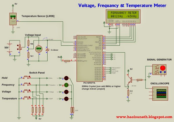 Timer 0 can only measure up to 256Hz, that is because timer 0 is 8 bit timer. Transistor part is use for safety of microcontroller from amplitude of wave signal. This circuit can apply 12v amplitude or more changing transistor base resistor value(4.7K). I tested it, using 12v amplitude square wave signal.
Troubleshooting…
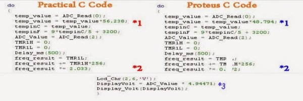
If you have problem about accuracy of voltmeter, temperature meter and frequency meter, you can change values (*1,*2,*3)
For more detail: Voltage, Temperature & Frequency Meter With PIC Micro controller
- What voltage range can the voltmeter measure?
The voltmeter can measure DC voltages up to 50V using a voltage divider that converts to 5V for the PIC. - How is the PIC microcontroller protected from high input voltage?
A 5V zener diode and a voltage divider (10K and 1.1K) are used to protect the PIC analog input. - What temperature range does the temperature meter support?
The temperature meter is described as usable between 0°C to 1500°C, and the LM35 sensor range noted is -55°C to 1500°C. - How does the temperature sensor output relate to temperature?
The sensor output voltage increases with temperature, giving maximum voltage at maximum temperature and minimum voltage at minimum temperature. - What is the maximum measurable frequency?
The frequency meter can measure up to 65 kHz using Timer1 (16-bit) of the PIC microcontroller. - Why can't Timer0 be used for high frequency measurement?
Timer0 is an 8-bit timer and can only measure up to 256 Hz, so it is unsuitable for high-frequency measurement. - How is the microcontroller protected from high-amplitude frequency signals?
A transistor stage is used to protect the microcontroller from the amplitude of the input wave signal. - Can the circuit handle 12V amplitude signals?
Yes; the circuit can handle 12V amplitude square waves by appropriately choosing the transistor base resistor value (4.7K was used in testing). - Can each function be paused?
Yes, every function can be paused using a push button. - What can be adjusted if accuracy is poor?
If accuracy problems occur with the voltmeter, temperature meter, or frequency meter, you can change specified component values marked in the document (*1, *2, *3).
