Summary of Lecture 43 : Interfacing PIC16F877 Microcontroller with an LCD
This article details the process of interfacing a Displaytech 162A LCD with a PIC16F877 microcontroller to display "IITK." It outlines necessary hardware components, software tools like MPLAB IDE, and a step-by-step procedure involving code writing, simulation, burning the hex file, and physical circuit assembly. The text explains LCD initialization steps, including command execution and data writing to DRAM locations using specific timing diagrams.
Parts used in Interfacing LCD with PIC16F877:
- MPLAB IDE
- PIC BURNER 3
- LCD (Displaytech 162A)
- Computer System with Windows operating system
- RS 232 cable
- PIC16F877 Microcontroller
- +5V D.C Power Supply
- Resistors - 10K Ω-1, 50Ω-1
- Capacitors - 27 µ F-2
- Potentiometers - 10K Ω -1
- 20MHz Crystal oscillator
- SPST switches -1
To interface LCD (Displaytech 162A) with PIC16F877microcontroller and to display “IITK” in the Liquid Crystal Display (LCD).
- MPLAB IDE (PIC microcontrollers simulator)
- PIC BURNER 3 with software to load the code
- LCD (Displaytech 162A)
- Computer System with Windows operating system and RS 232 cable
- PIC16F877 Microcontroller
- +5V D.C Power Supply
- Resistors – 10K Ω-1,50Ω-1
- Capacitors – 27 µ F-2
- Potentiometers – 10K Ω -1
- 20MHz Crystal oscillator
- SPST switches -1
- Write the assembly code in MPLAB IDE simulator , compile it and check for errors
- Once the code was error free, run it and check the output in the simulator.
- After checking the code in the simulator, load the code (in .HEX format) into PIC16F877 microcontroller using PIC BURNER3.
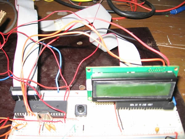
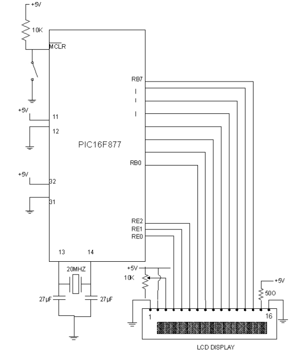
- Make connections as shown in the circuit diagram.
- Switch on the power supply and observe “IITK” displayed in the LCD.
Liquid Crystal Display (LCD-Displaytech 162A )LCD Displaytech 162A consists of a LCD panel, a controller IC (KS0070B) and a back light LED. The LCD module consists of total 16 pins in which, 2 are for power supply, 2 pins for Backlight LED, one pin for contrast adjustment, 3 pins are for control signals and 8 pins are data pins. In order to display any data, we need to do certain initiations. The following are the main three steps in displaying any data in the LCD display.
- Initializing LCD by sequence of instructions
- Executing commands depending on our settings in the LCD
- Writing data into the DRAM locations of LCD in the Standard Character Pattern of LCD
For doing above steps, refer the manual for LCD and follow the instructions and timing diagrams strictly.
MPLABIDEMPLABIDE is a free software which can be downloaded from the website www.microchip.com
Working with MPLABIDE :
MPLABIDE is a simulator for PIC microcontrollers to write and edit the code in assembly language, compile it and also to run the code. Output can be verified using simulator.
For more detail: Lecture 43 Interfacing PIC16F877 Microcontroller with an LCD
-
What is the primary aim of this project?
To interface an LCD (Displaytech 162A) with a PIC16F877 microcontroller and display IITK on the Liquid Crystal Display. -
Which software is used to write and compile the assembly code?
MPLAB IDE is used to write, edit, compile, and simulate the code for PIC microcontrollers. -
How is the compiled code loaded onto the microcontroller?
The code in .HEX format is loaded into the PIC16F877 microcontroller using PIC BURNER 3 after checking it in the simulator. -
What are the main three steps required to display data on the LCD?
The steps are initializing the LCD by a sequence of instructions, executing commands based on settings, and writing data into the DRAM locations. -
What specific controller IC is inside the Displaytech 162A LCD module?
The LCD module consists of a controller IC known as KS0070B. -
How many pins does the LCD Displaytech 162A module have in total?
The LCD module consists of a total of 16 pins. -
What frequency crystal oscillator is required for this setup?
A 20MHz Crystal oscillator is required for the project. -
Can the output be verified before connecting the hardware?
Yes, the output can be verified using the MPLAB IDE simulator before loading the code onto the actual microcontroller.